Let the hacking begin
My first bar hack
The first bar I built was a hodge-podge of ideas. Looking back I see some good ideas and some good execution but some parts of the design are clunky. This is that very first bar.
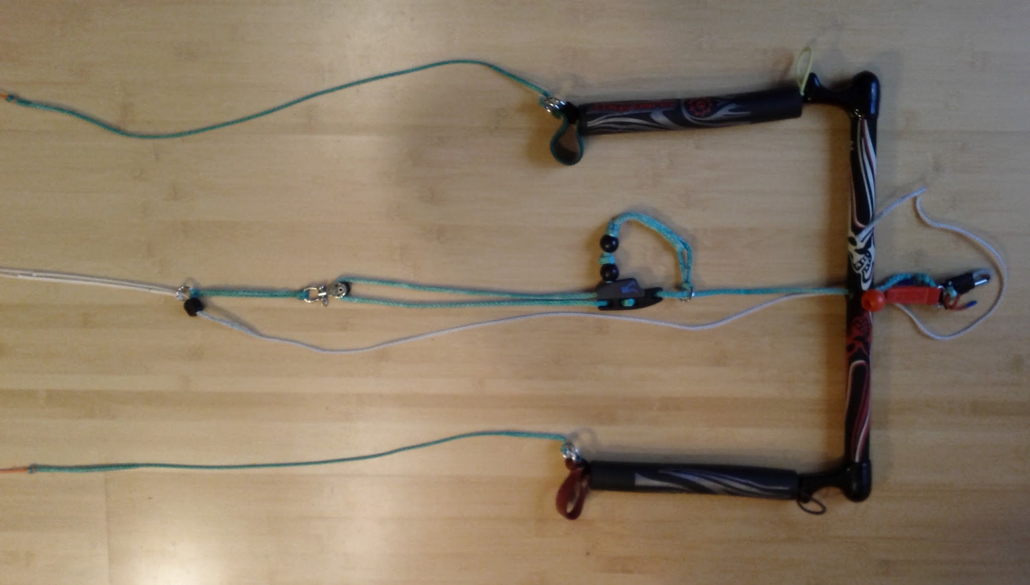
Trim control
At the center of this bar is the CL826-11AN Aero cleat from Clamcleat. This would be a common component in bar designs to follow. Its also popular in lots of commercial bars. It is beautifully engineered and reasonably priced. This model accommodates line 4-6mm in diameter. The green trim line passing through it is 3/16” (5mm) AmSteel-Blue Dyneema Single Braid. The black balls are fixed in place with figure eight knots. The end of the 5mm AmSteel is spliced into itself and stitched to form a loop. All of that is good.
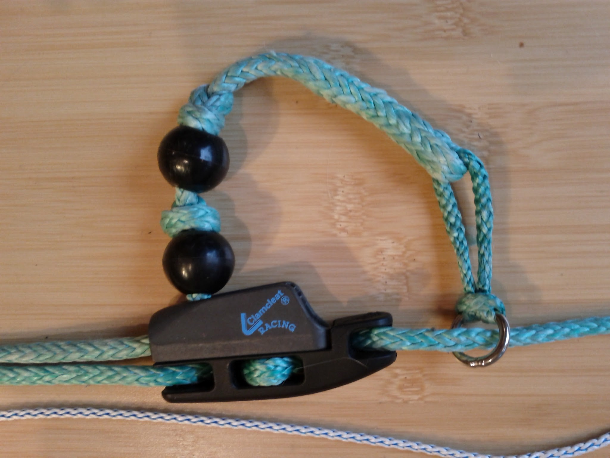
Attached to the loop at the end of the trim line is a short segment of spliced 7/64” AmSteel with a 1/2” Stainless steel ring larksheaded on. The tensioned portion of the trim line on the right of the Aero cleat passes through the ring to keep the tail of the trim line affixed to the trim line. That latter aspect is good, but I have no idea why I used the short segment of 7/64” AmSteel. It is needless complexity. The simpler design is to affix the ring directly to the end of the trim line. I do that in subsequent designs.
At the bottom of the photo of the cleat is a 4.5 flag line. This line connects one of the main flying lines to the leash to allow the kite to flag on the main flying line when the bar is released from the harness. There are flaws with this flag line. The line’s path is not well-controlled. There is nothing to prevent the flag line from moving into the jaws of the cleat and getting caught in the cleat when the trim line is adjusted. This would prevent the flag out and render the flag line useless. The trim line should be low on the sides of the cleat or below the cleat to keep it from fouling in the jaws of the cleat.
The flag line’s other flaw is the lack of continuous tension. While not readily apparent in this photo, there is no means to keep the flag line taught as the kite trim is changed. When trimmed in, the flag line can form loops that wrap around the cleat or the end of the trim line. The trim line end can also pass through loops in the safety line. These situations can make flagging unreliable and trimming impossible.
Main flying lines
The main flying lines come together at a 1/2” welded stainless steel ring. One line is larks-headed to the ring while the other passes through the ring. The pass-through line then passes through a small bore hole in a Delrin ball and connects to the 4.5 line via a larks head knot. The bore through the ball is stair-stepped so the side with the 4.5 line can accommodate the larks head inside the bore. The larks head is stopped by the step-down in diameters inside the ball. The ring and ball are sized so the ball will press tightly against the ring under flying load. The ring is, in turn, connected to a small pulley via a small segment of 7/64” AmSteel. The pulley allows the trimline to move freely when adjusted.
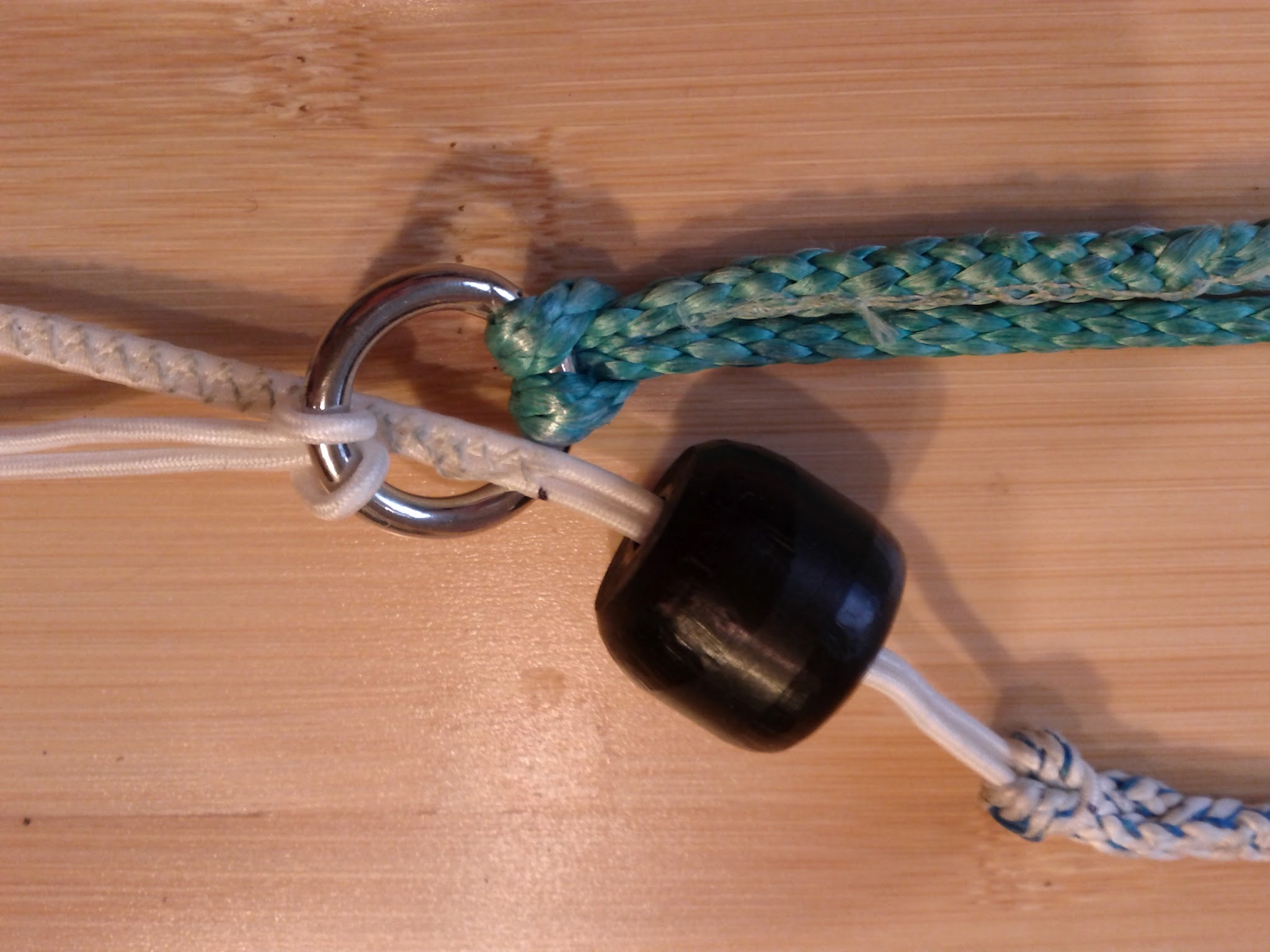
This is pretty reliable engineering, but there are some fine details that must be carefully executed to make it work correctly. The flying line ends in this bar are folded and stitched. This makes the line end relatively small. This is required because the 4.5 line must be fatter than the flying line so that the larks head knot can jam against the ball. Yet that larkshead needs to pass through other bar components and they have diameter constraints. If the 4.5 line is too fat the larkshead can jam in other parts of the bar during release.
The small hole of the stair stepped bore-hole inside the ball has to be sized to the flying line end. It has to be large enough to accommodate the finished end of the flying line, but no larger. The flying line must pass through the bore-hole unimpeded during release. If the hole is too small, the flying line can snag on release. If the hole is too large, the larks head can get pulled into the small bore, jam and prevent release. If the hole is larger still, the 4.5 line can pass through it under the load from the kite and cause the kite to collapse or spin uncontrollably. In either case it would prevent activation of the safety system and be very dangerous.
The last detail not readily apparent from the photo is the relationship of the main flying lines. The terminate differently with one larkes headed to the welded ring while the other is retained by the larkshead to the 4.5 line stopped iside the bore of the ball. The large side of the bore hole should be large enough and deep enough to allow the larks head to nestle inside the ball near the mid-line. This keeps the offset of the mains near zero.
The chickenloop
The flyer’s end of the trim line is terminated in a figure eight knot. The loop of that knot is routed into the upper loop of a very small chicken loop. A stainless steel pin passes through the trimline loop and into the body of the chickenloop. A red webbing handle and ball (not visible) on the end of the pin provide the release mechanism. The lower end of the chickenloop has a slightly larger loop big enough to clip to a carabiner on the flyer’s harness.
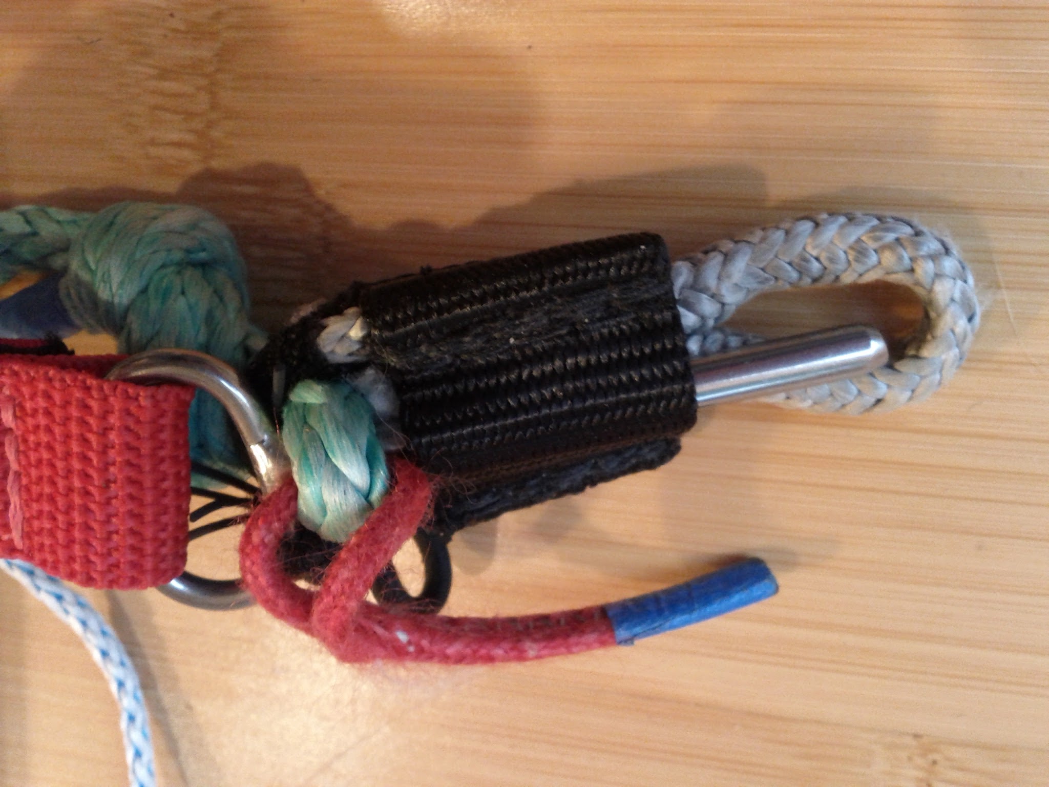
This design benefits from being very short. This keeps the bar and trim control close to the pilot without reducing bar-throw. The chickenloop also allows for quick release, but beyond these two good features, there are problems. It does not include a swivel to allow the mains to be untwisted. The pin was tethered with elastic, but nothing else. This allows the pilot to rip the pin off the chickenloop during release and potentially loose the pin.
Steering lines
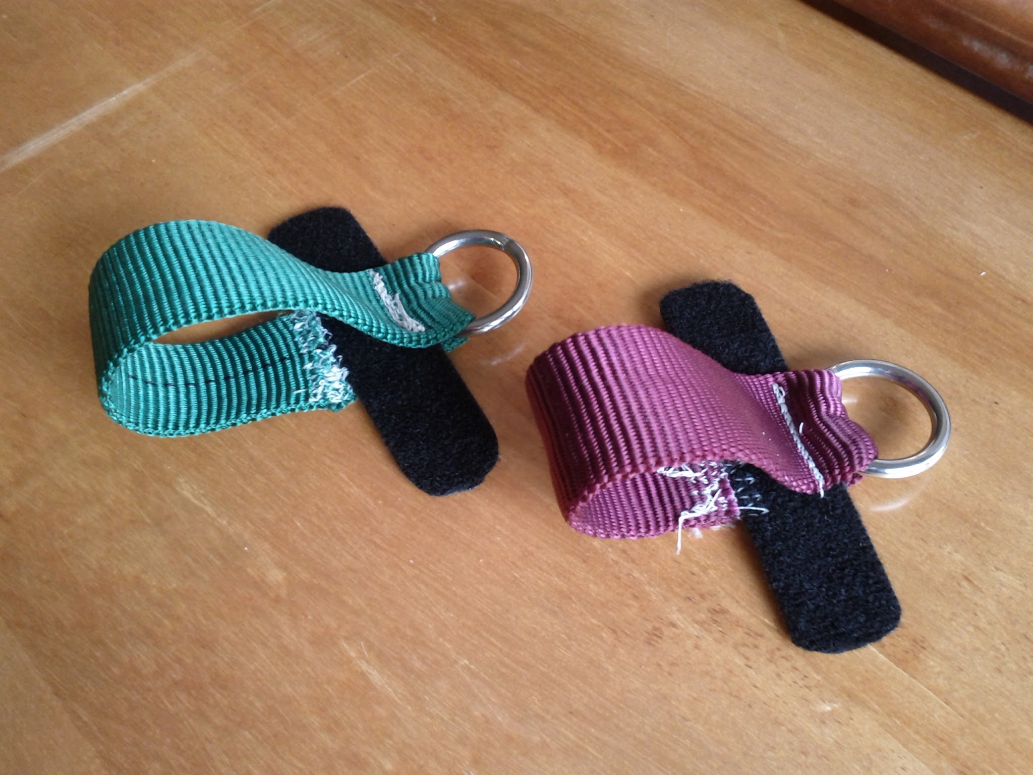
The steering lines of this bar are equipped with self-landing handles. Each is constructed with two same-sized welded rings. The flying line is larksheaded to a leader of 7/64” AmSteel. The leader is routed through a ring and then is larksheaded to a second ring of the same size. The first ring is larksheaded to another leader that routes through floats to the bar. The second ring–the one that connects to the kite-side leader–is stitched to a small loop of tubular webbing to form a handle. A small piece of hook and loop fastener is stitched to the webbing loop so the handle can be loosely affixed to the bar-side leader. The hook and loop fastener is weak enough to separate under several pounds load yet strong enough to keep the steering lines in order when not under tension.
The floats in this design are almost completely useless for landing kiting. They are minimally useful for hauling in on the steering lines, yet are too short to haul in much line. Steering leader lines are typically a meter long. If made from 7/64” line they can easily be pulled with gloves.
The self-landing handles are useful but add complexity to the construction. They require the construction of twice as many steering line leaders. A more interesting design might be to use very short leaders on the bar and near full length leaders on the line-side. They could be assembled with or without self-landing handles. The change to the steering line length would be negligible compared to the available bar throw and trim control.
