State of the Bar Art - September 2018
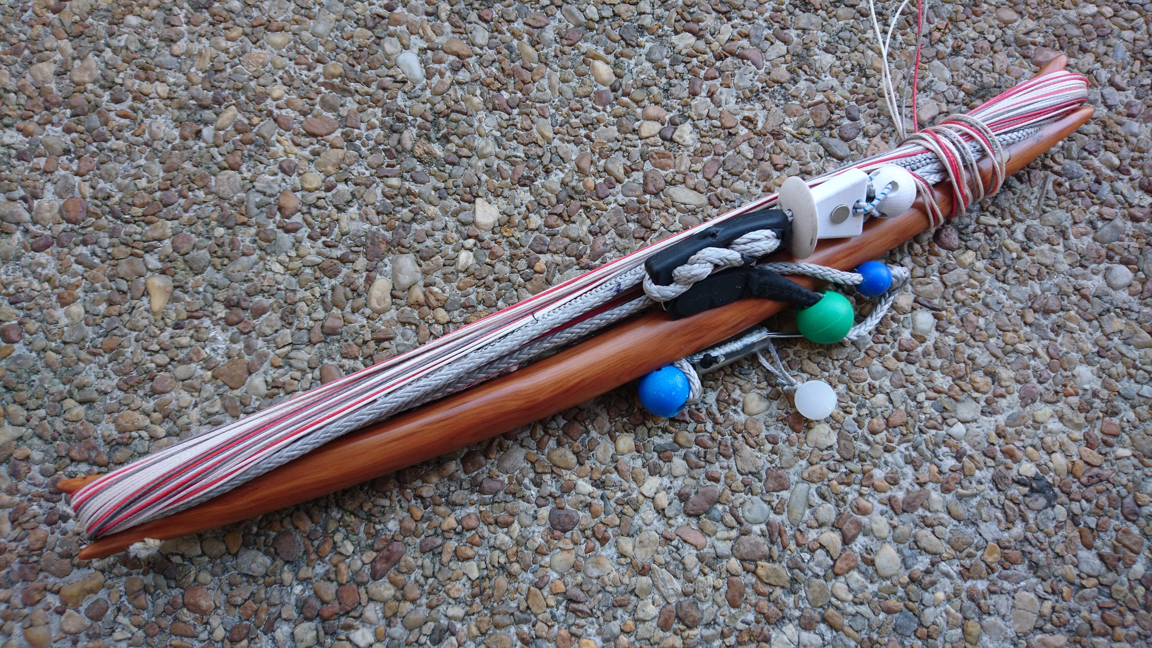
I’ve had made a lot of changes to the way my bars and harness are built in the past year. I’ve covered the harness in recent articles, but I haven’t said much about the bar save for Printing a moveable stopper in June of this year. Some of the revisions are described in 3D models of components for kite control bars though that is focused more on the models than explaining why they are the way they are and how they work with everything else. I hope this post can shine some light on recent developments with a nod toward the overall design concepts.
Magnetic trimline tail
In earlier designs the tail of the trim line was tethered to ring that rode between the moveable stopper and the cleat. This worked well pretty well to keep the trim line from tangling in other things, but it prevented large, swift changes in trim.
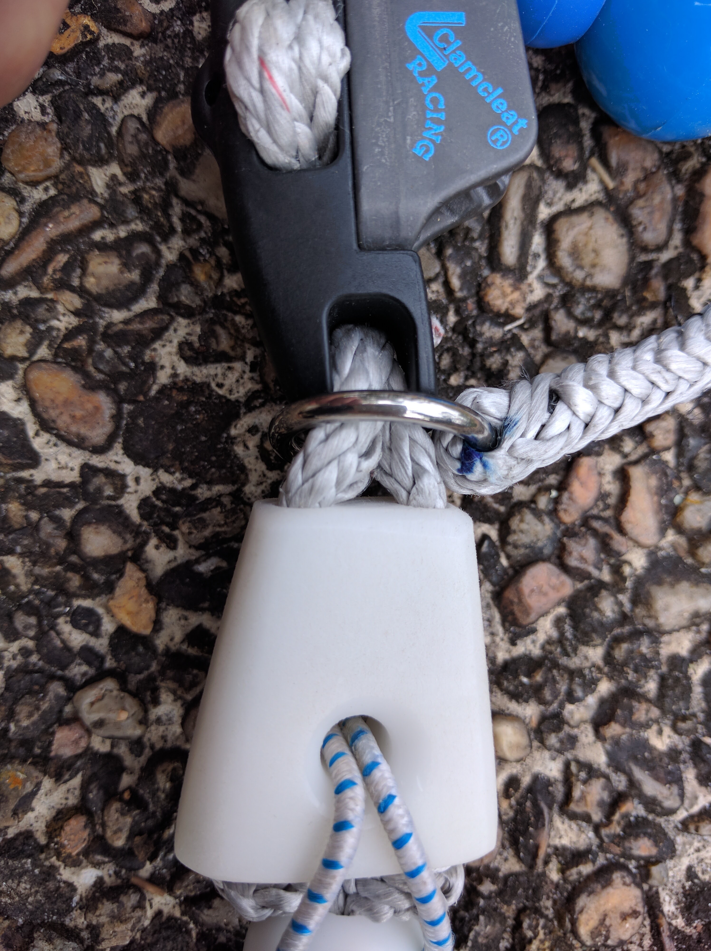
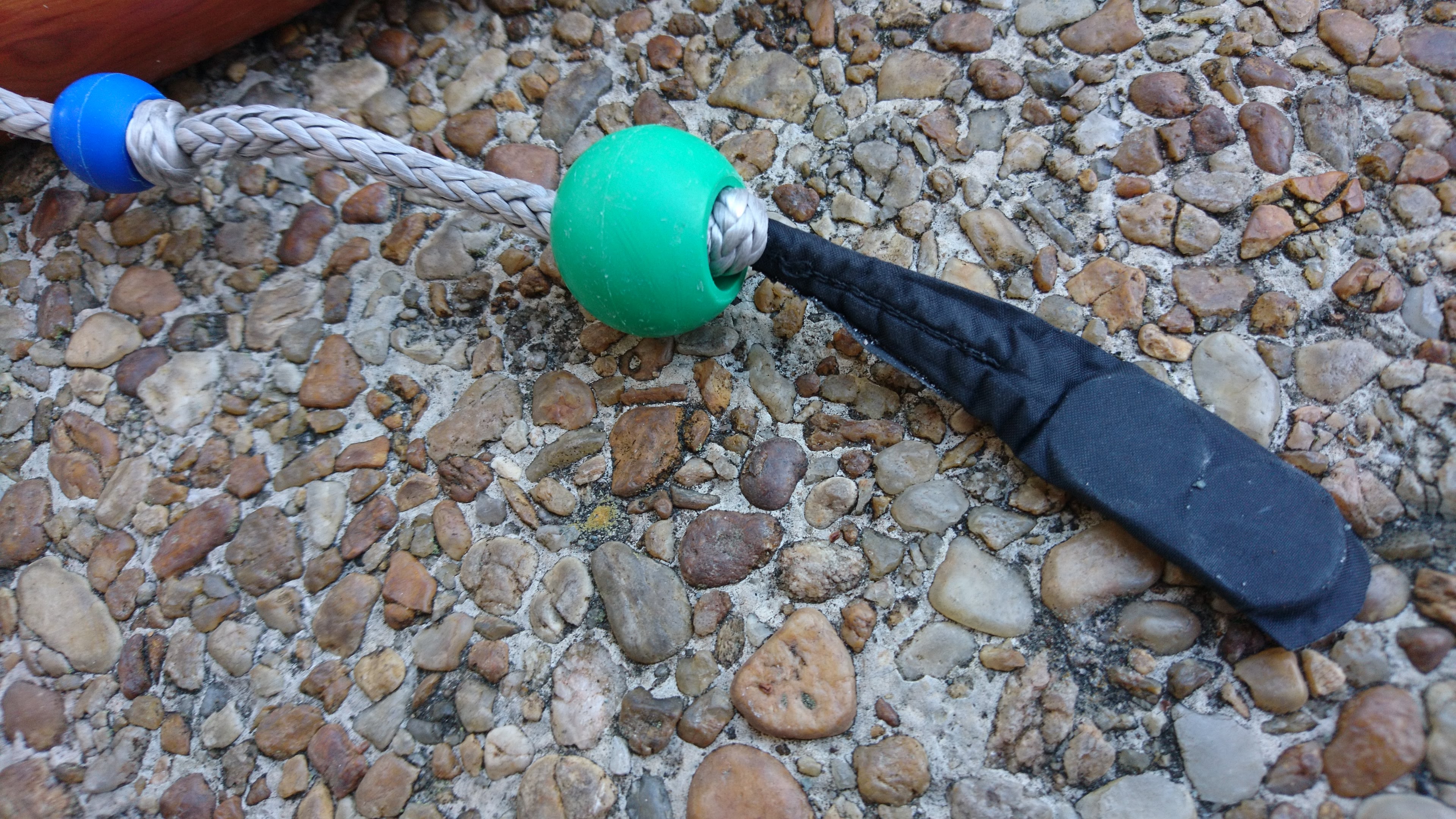
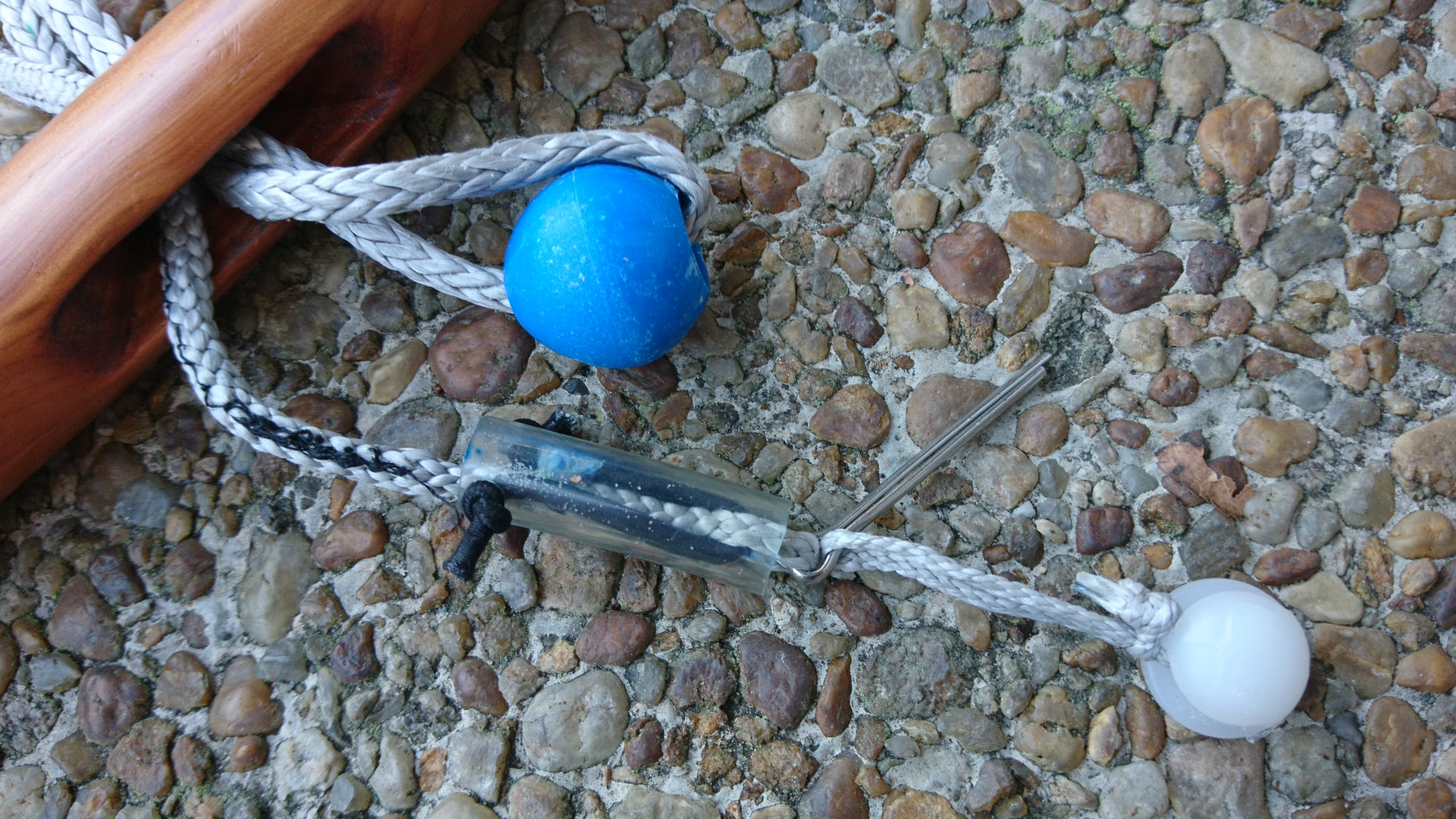
To get those quick trim changes you have to free the end of the trim line. The problem is keeping the tail out of troubled when you’re not holding it. To address this, I resorted to magnets. I’ve seen these go to hell from corrosion on kite surfing bars, but so far I have had no issues. I’ve used only nickle-plated neodymium magnets to improve my corrosion resistance. I don’t rinse my bars after use, but neither do I go into the ocean so it’s unclear if I am smart or just lucky.
The first set of magnets goes into the tail of the trim line. I use a pair of flat, round neodymium magnets about 3mm x 15mm. The magnets sit edge-to-edge just below the end of the trim line wrapped in peel-and-stick insignia cloth that reaches from below the lower magnet to about 30mm up the trim line. I stitch the cloth to the trim line to make sure it doesn’t creep.
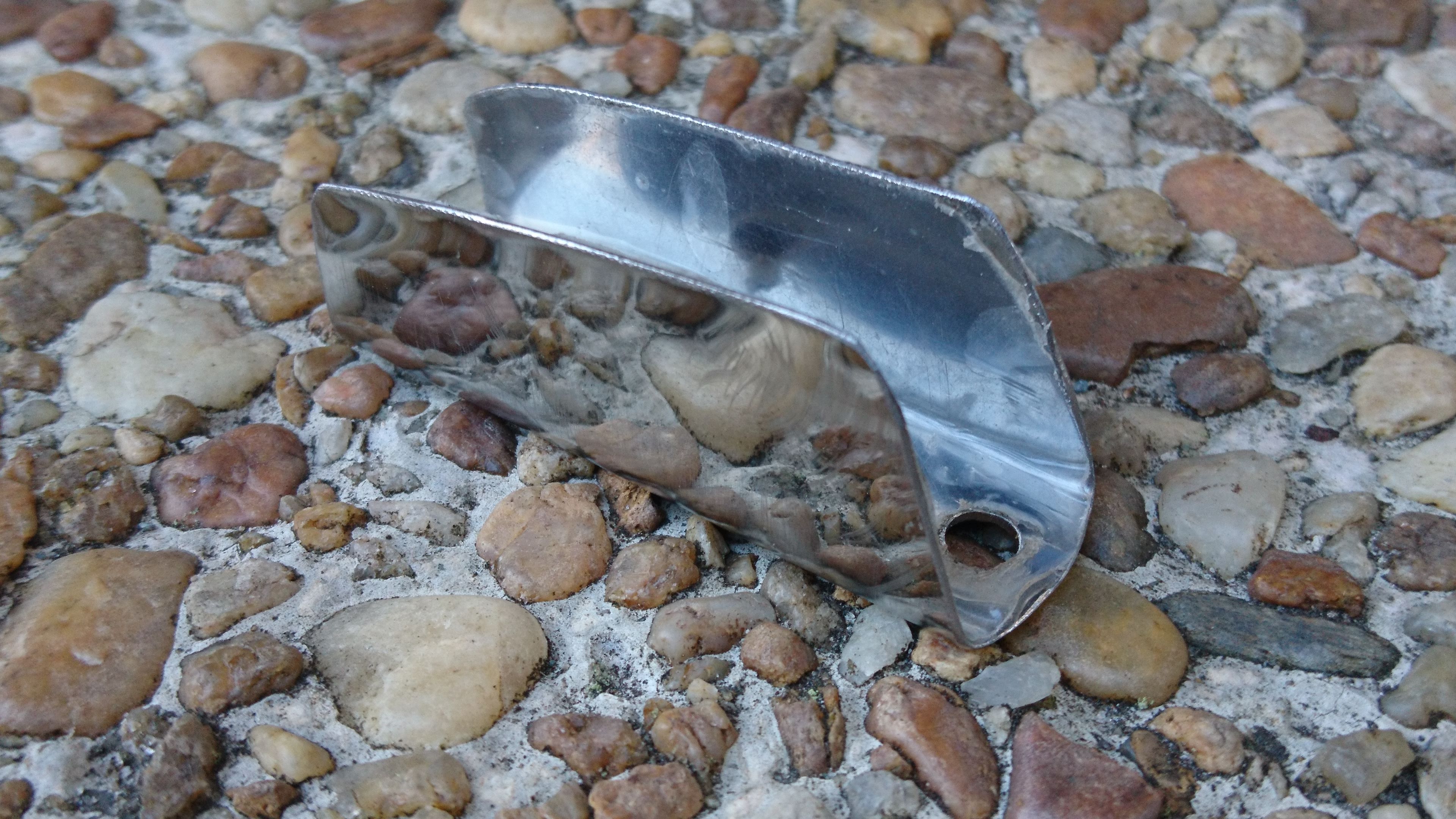
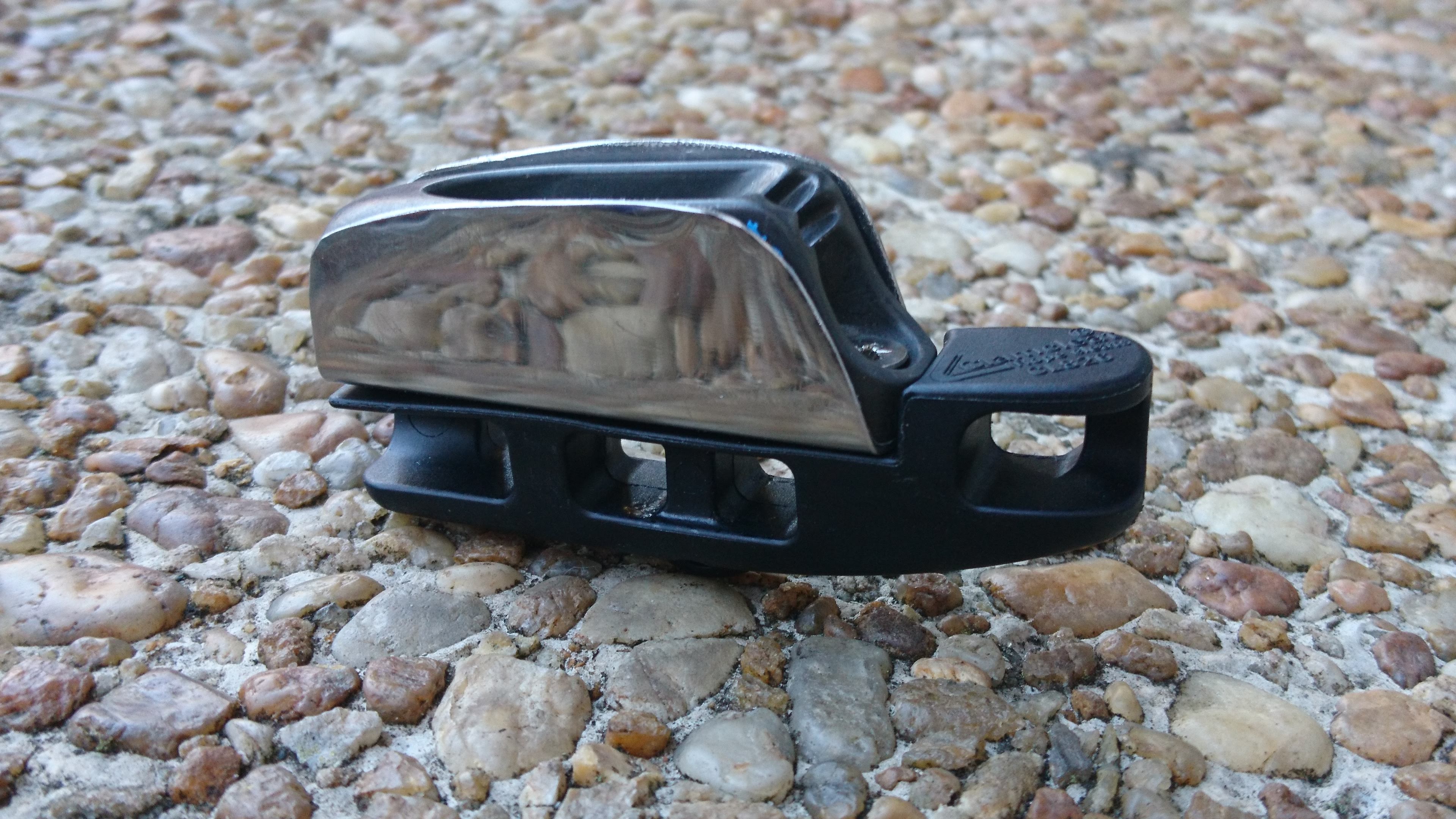
The magnetic trim line is at best half the solution as the magnet needs something to stick to. As my bars had no ferromagnetic steel in them much less magnets, I had to add that. I’ve had good results with a jacket of ferromagnetic stainless steel wrapped around the sides of the cleat portion of the ClamCleat. McMaster-Carr sells ferromagnetic 430 Stainless Steel Sheets that can be cut, drilled and bent to form a U-shaped jacket around the cleat. There’s a little bit of an electrolytic reaction between the aluminum cleat and the stainless steel, but it appears to be slow. The jacket allows the trim line to stick to either side of the cleat in any orientation. The end of the trimline stays out of the jaw of the cleat and out of the path of the flag line.
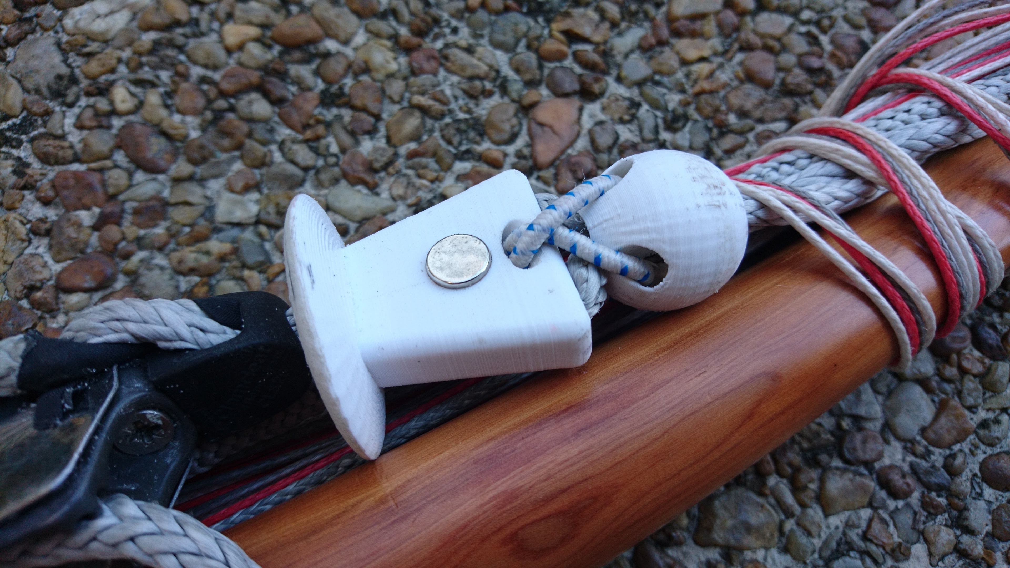
To provide an alternative way to tether the trimline end, I also placed another neodymium magnet in the moveable stopper. I use a 3/8 inch x 3/8 inch cylindrical magnet pressed into the center of the stopper. The magnet is exposed on the face opposite the flag line to keep it from pinching or impeding the motion of the flag line or the stopper.
Separation blocks
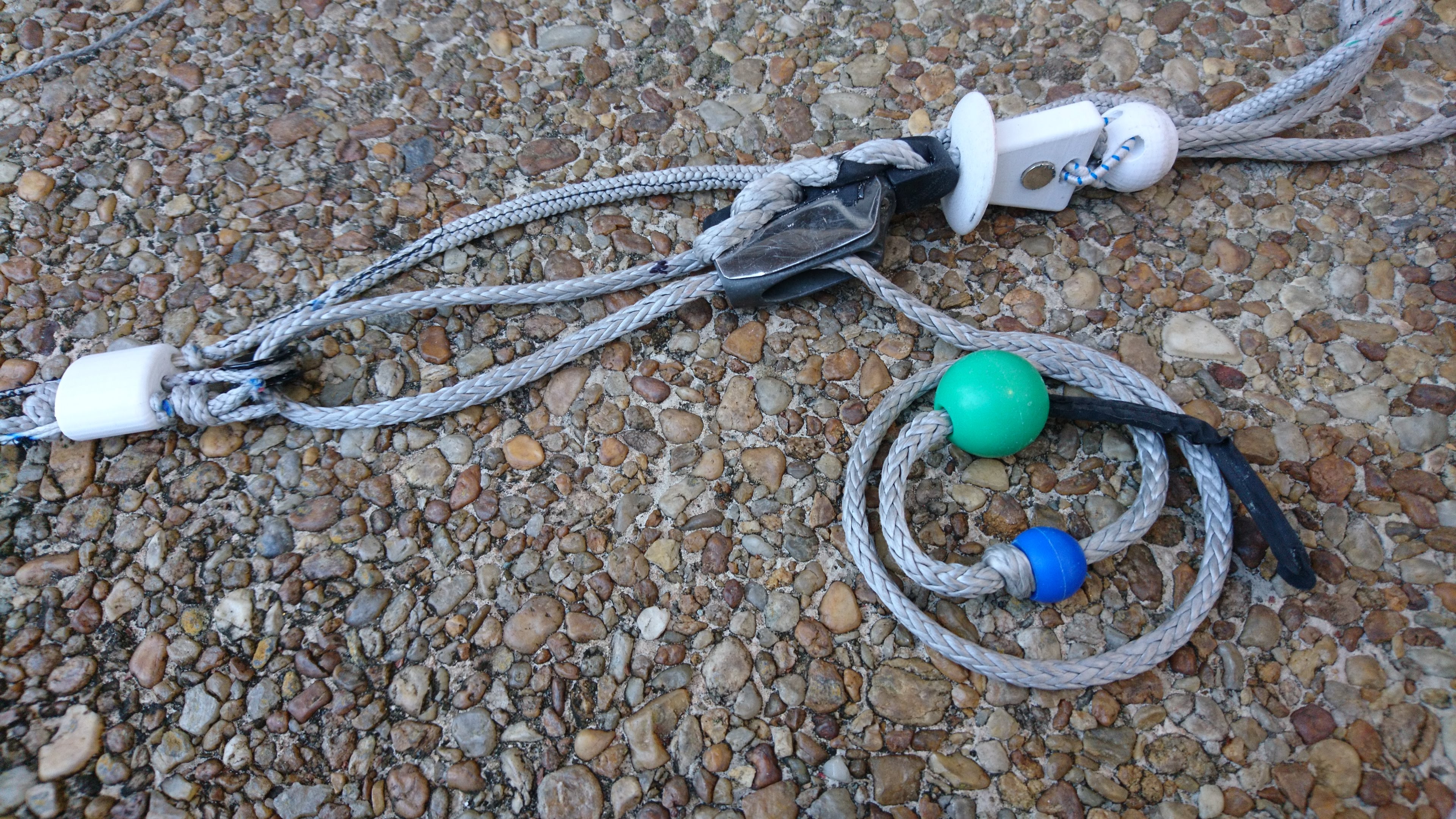
I refer to the juncture of the flying lines, trimline and flag line as the separation block. It has narrow passage ways for the flying to pass through, room to anchor the flying lines with larkshead stoppers, and a pulley for the trim line. In my earlier designs I used a segment of 4mm Spectra/Dyneema as the pulley. While this works, the trim line slowly saws through the “pulley”. Despite the block’s relative simplicity, machining it from Delrin is time consuming and error prone.
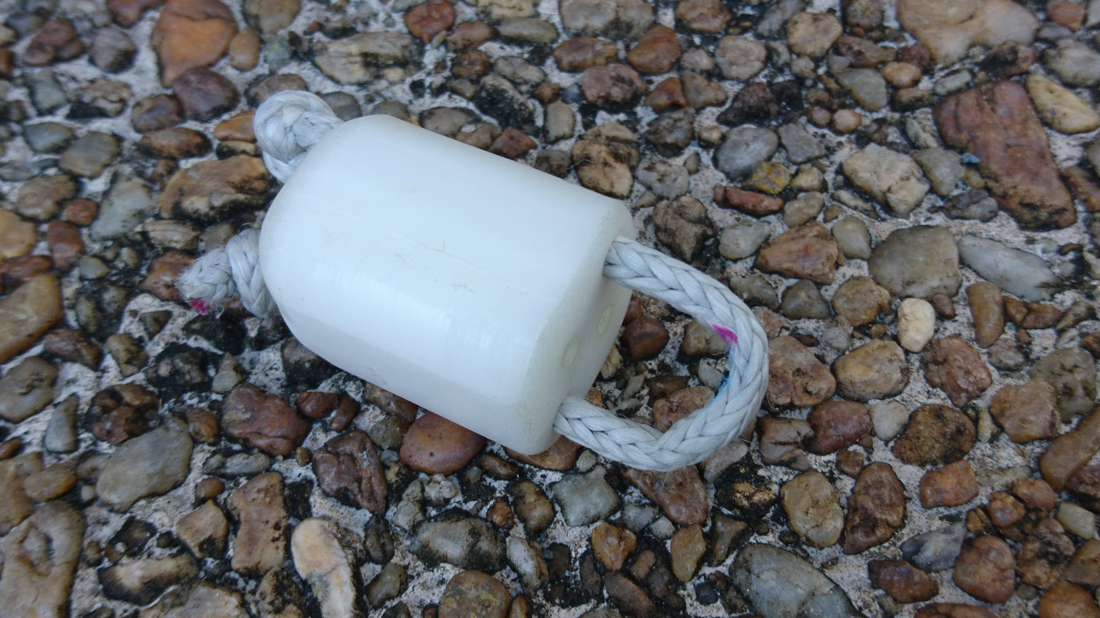
To address flaws in the pulley and simplify the manufacture of the block, I now 3D-print the separation block. The new design is smaller, more comfortable to grip and easier to make. Instead of a loop of line for the pulley I use a low-friction ring held by a line that passes through a single hole in the block. The design is well balanced, has low friction for the trim line won’t wear out as fast.
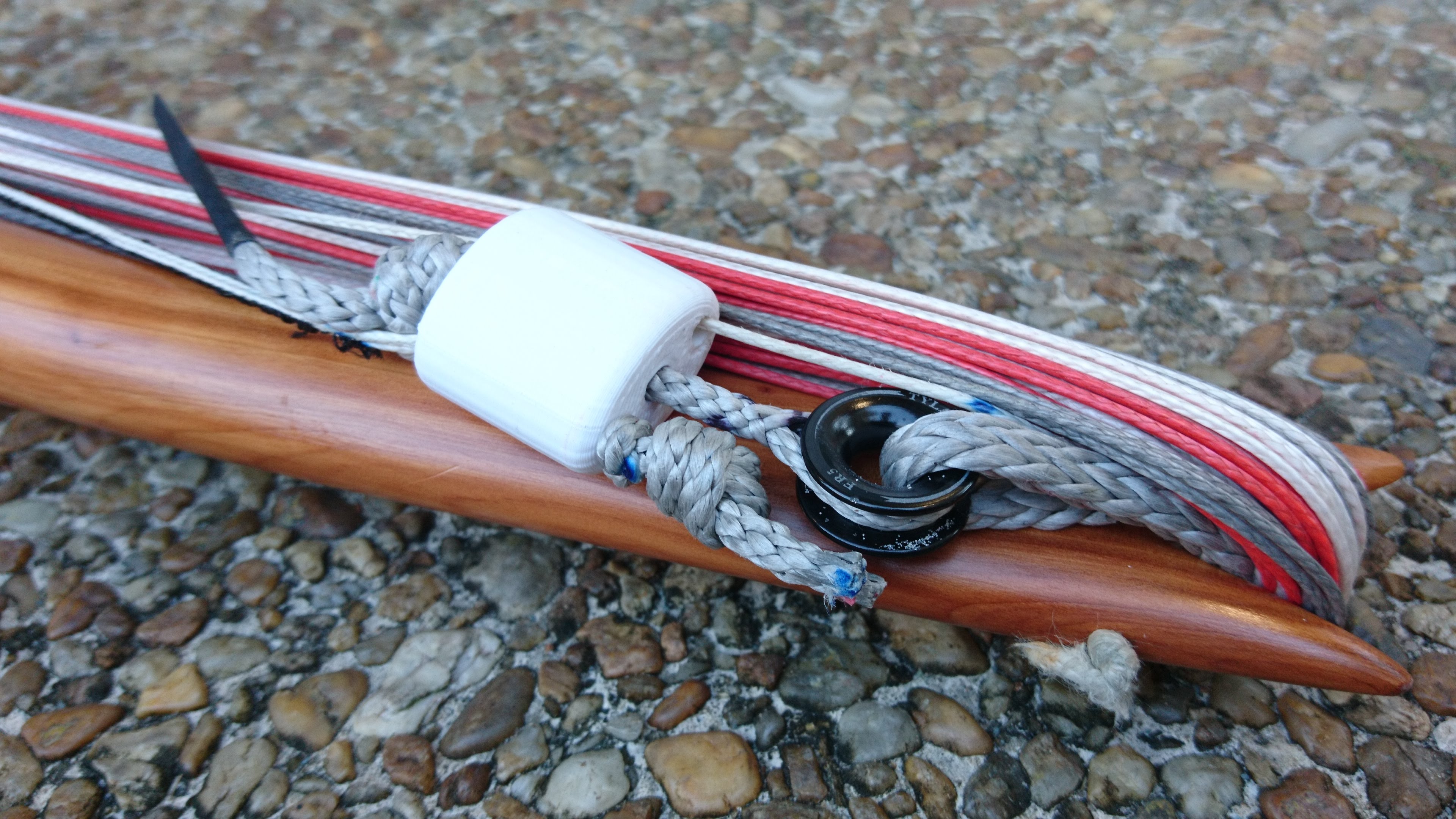
The separation block requires flying lines with clean, narrow ends. This allows the flagged flying line to move rapidly and reliably through the separation block and the rest of the rigging during a flag-out.
The clean, narrow flying line ends are best achieved by using hollow core flying line with spliced end loops. This creates the narrowest possible end with the least possible snags. It’s possible to get reasonable results by stitching folded line ends together or by tying a 200# - 300# Q-Powerline Pro line, but the spliced ends are the best method. Sleeved lines will not work in any form.
Elastic flag line
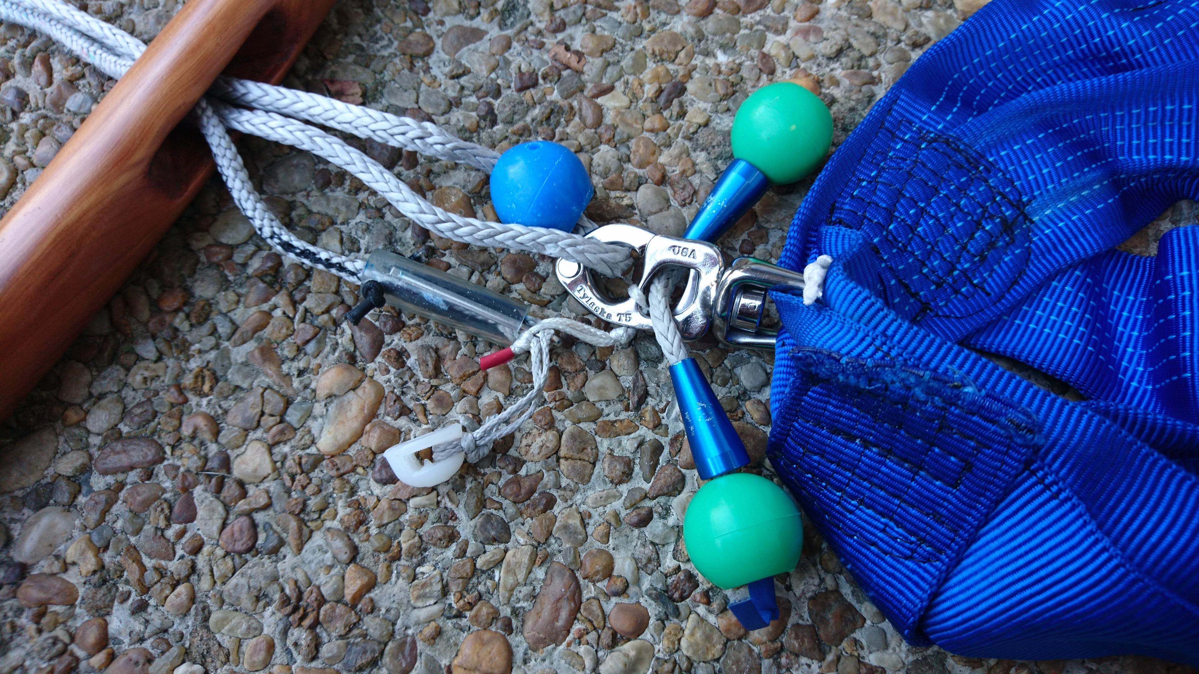
My bars incorporate a 4.5 line to allow the kite to flag out on one of the top lines when released. This flag line connects to one of the flying lines on the flyer’s side of the separation block, passes through a guide-path in the stopper, through the bar and terminates in a cotter pin release just below the bar. The cotter pin is designed to connect to a loop or ring on the backside of the snap hook on the flyer’s harness.

To keep the flag line from tangling in the cleat, stopper or other rigging, the line has an elastic core to keep it taught when the trim is pulled in. Yet the line is sized to allow the trim to go all the way out as well. This is a difficult constraint. Getting it right requires some planning and math that is best saved for another article. To assure the flag line doesn’t bunch up and jam in a narrow passageway, the jacket of the flag line has to be sewn to the elastic core while the flag line is fully stretched. This keeps the slack length of the jacket evenly distributed along the flag line. This is challenging sewing operation I have only been able to do on Tim Elverston’s commercial straight-stitch sewing machine. (Note: this is no longer true. The BuggyBar Build Book describes how to do this. –pbc, 2019-06-12)
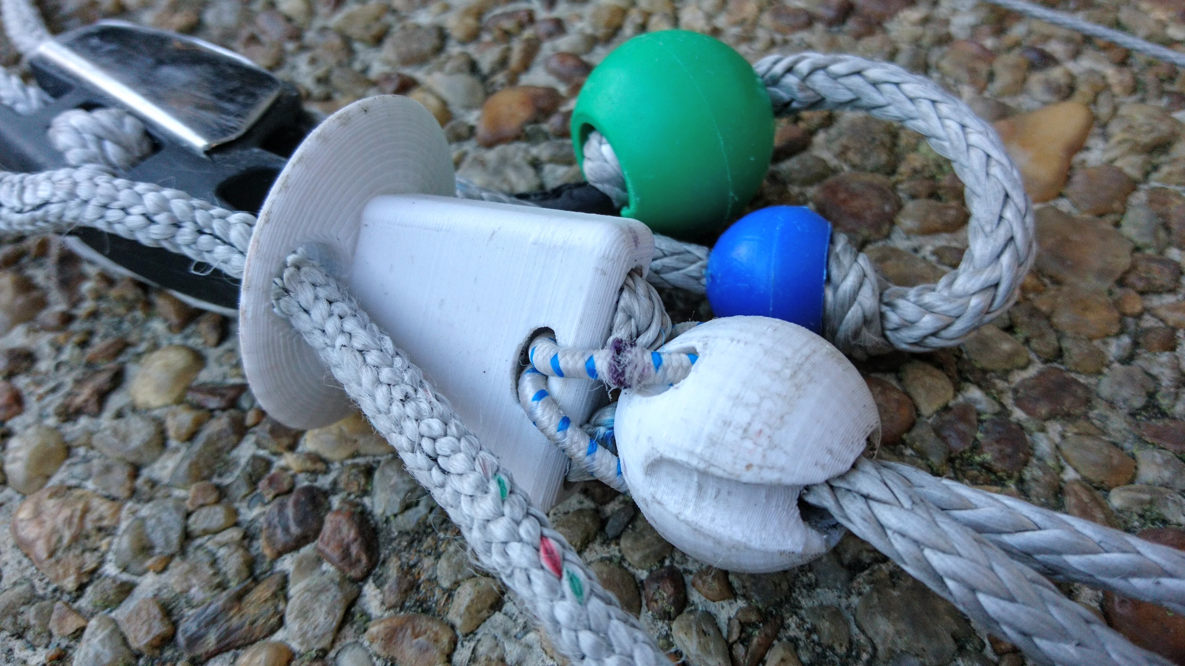
The end of the flag line provides both an attachment to the harness and quick release should the flyer need to separate from the flagged kite in an emergency.
Moveable Stopper
As with the separation block, the components of the movable stopper have always been hard to machine accurately from Delrin. The task has gotten worse with every feature added to the stoppers. In June I finally gave up on the idea of machining the stopper. I set aside the initial design that Andrew Beattie did in April of 2016 and started from scratch. The design has morphed 20 times since and now looks radically different.
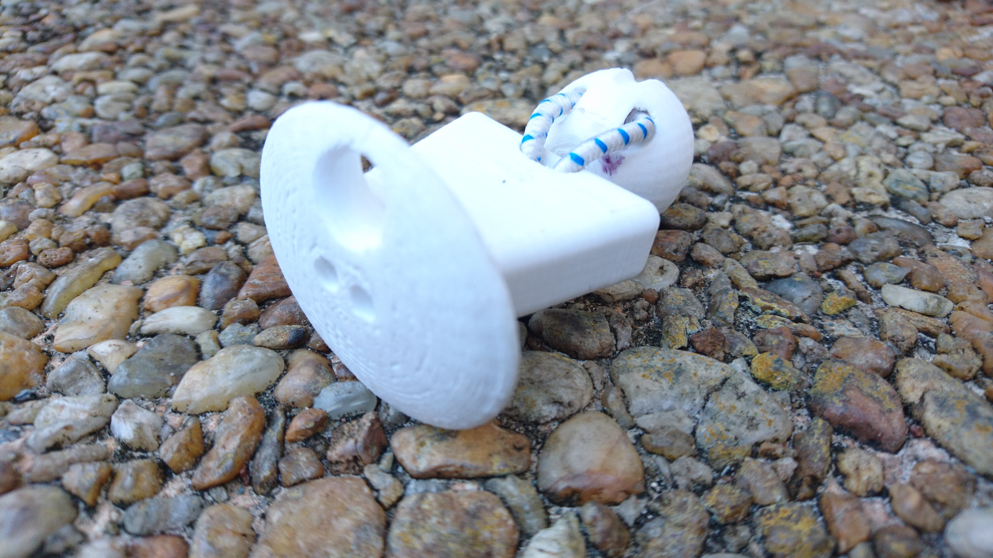
The stopper block provides two pathways for the doubled trim line. It forces the lines apart on the flyer side, then back together on the cleat side. A stopper ball just below the block squeezes the trim lines back together to prevent the pressure of the bar from moving the block. A cross bore through the stopper provides an attachment point for attaching the ball to the stopper. The curved path of the cross bore allows the bungee that connects the ball to the stopper to move freely and balance the tension in the bungee.
The 360-degree flange provides a continous surface to push the stopper away no matter its orientation. A large bore in the flange provides a pathway for the elastic flag line. On the opposite side of the block is a socket for a neodymium magnet. This magnet provides an additional location to the tether the trim line. Placing it opposite the flag line path keeps the trim line away from the flag. As the block can be oriented relative to the cleat, the flag line pathway through the flange also directs the flag line to the underside of the cleat away from the cleat’s jaws.
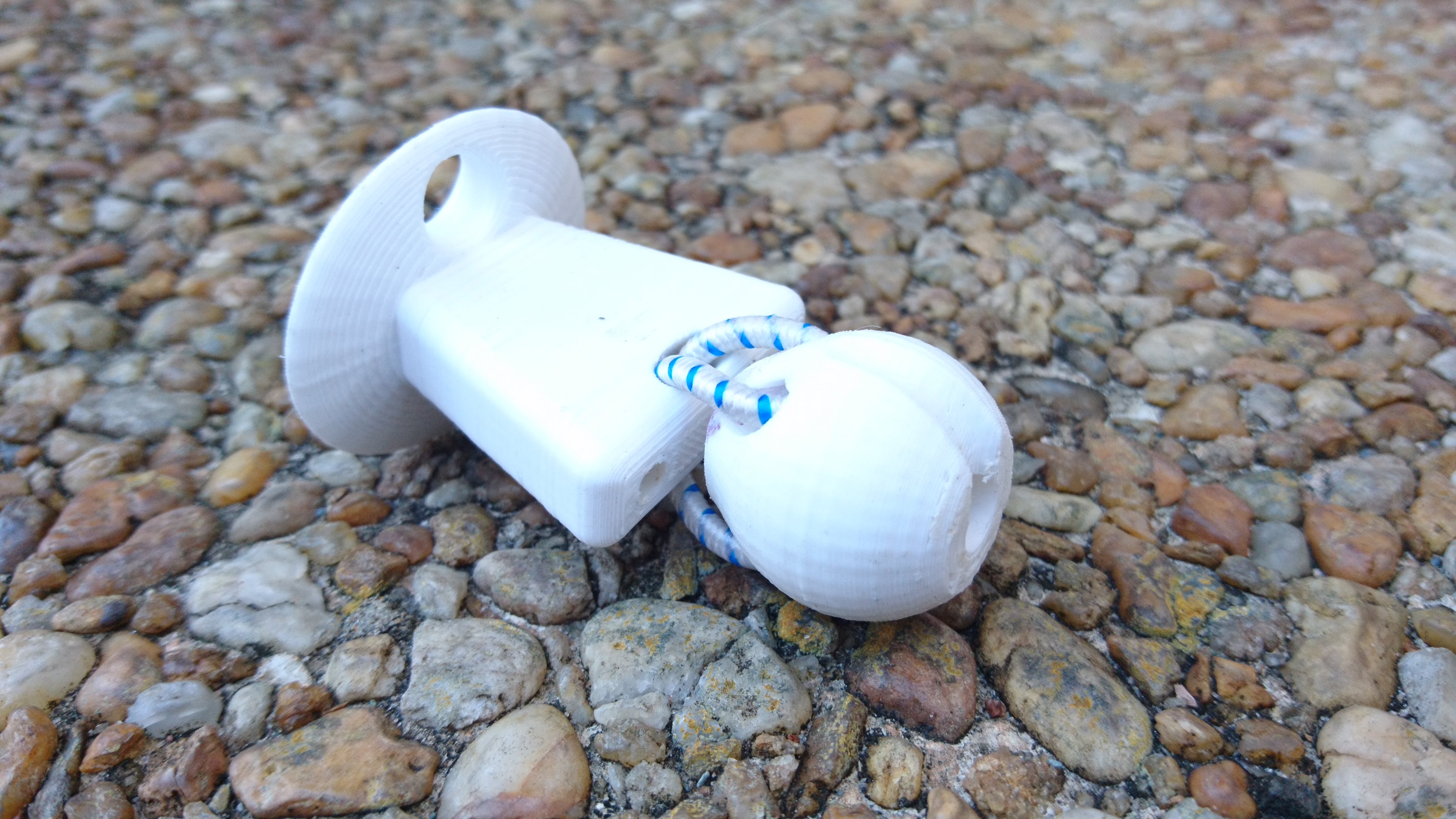
The stopper ball sits a few millimeters below the stopper block connected via a short segment of bungee. After the trim lines emerge from the block they are both routed though the center bore of the ball.
When the bar presses the ball upwards against the block, the ball and block form a kink in the trim line that completely stops the ball’s movement. The connection between the block is 115mm (?) of 1/8” diameter bungee. The bungee is routed through curved paths in both the block and the ball. The path forms a continuous loop of bungee. The ends of the bungee are cut blunt and super-glued together to ease the movement through the pathways and eliminate knots.
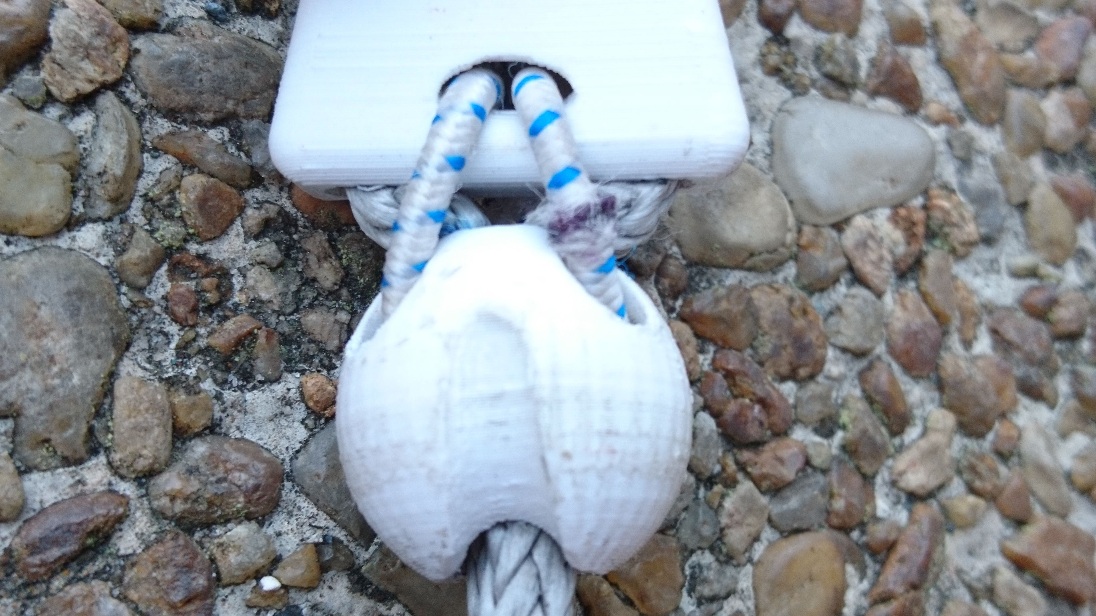
The lower, hemispherical portion of the ball is designed to mate with the round center-bore of the bar. These surfaces allow the bar to spin freely about the ball. The hemisphere is notched on one side to provide a path for the flag line. The notch is deep enough to allow the flag line to move past the ball and through the bar even when the bar presses tightly against the ball. Similarly, the notch prevents the flag line from impeding bar spins.
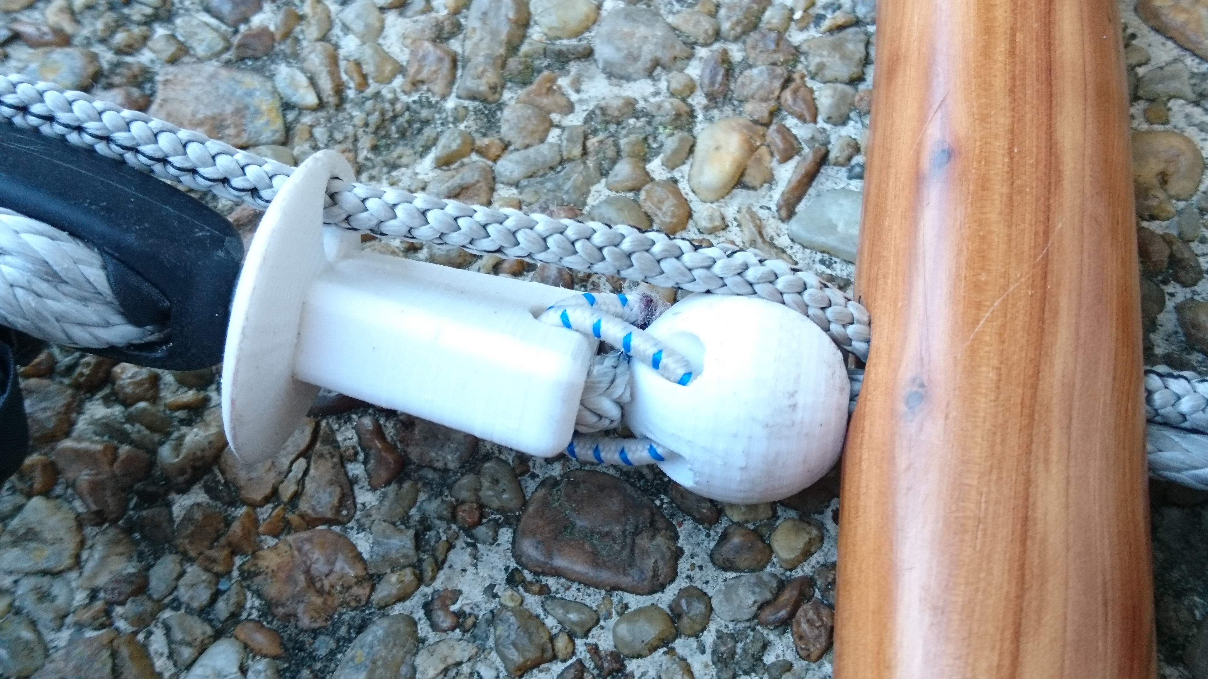
The routing path for the bungee controls the ball’s orientation relative to the block. This allows the flag line notch in the ball to be permanently aligned with the flag line path in the block. This passively aligns the flag line with the notch to ensure a straight, unimpeded path through stopper components and bar.
Bar assembly and threading line
All of these components are assembled on a trimline of 4mm Amsteel Blue. In some bars I have tried 5mm Amsteel, but the 4mm is easier to route through the cleat. The trim line is 2275mm in length. The trim line magnets have to be affixed to one end. The other end will need to be threaded through some long, narrow passageways in the cleat and stopper. To simplify this work, wrap a bit of insignia cloth around the end of the trimline. Cut a strip 20 mm wide and 65mm long. Wrap the insignia cloth tightly around the last 20mm of the trimline, forming a tail of flat cloth 45mm long on the end of the line.

To thread the trim line, put the threaded end through the cleat entering at the jam side. Exit the cleat at the top, routing up through the low friction ring of the separation block. Reenter the cleat and go through its serpentine path. Leave just enough line above the cleat to provide the desired trim. Route the line through the stopper block, then ball. Go down through the center of the bar, through a ~25mm ball to retain the trim line in the bar. Then go back through the center bore of the bar, through the stopper ball and then the stopper block. Slide the stopper ball down towards the bar to leave lots of slack above the stopper. Before going any further, make sure the line already passing through the cleat’s serpentine has 5 cm of loop on each side of the cleat. You’ll need this slack in the next step.
Then route the loose end of the trim line up through the cleat’s serpentine path. You want to make large parallel loops of line going back and forth through the serpentine. Route about 5cm of the trim out of the top of the cleat.
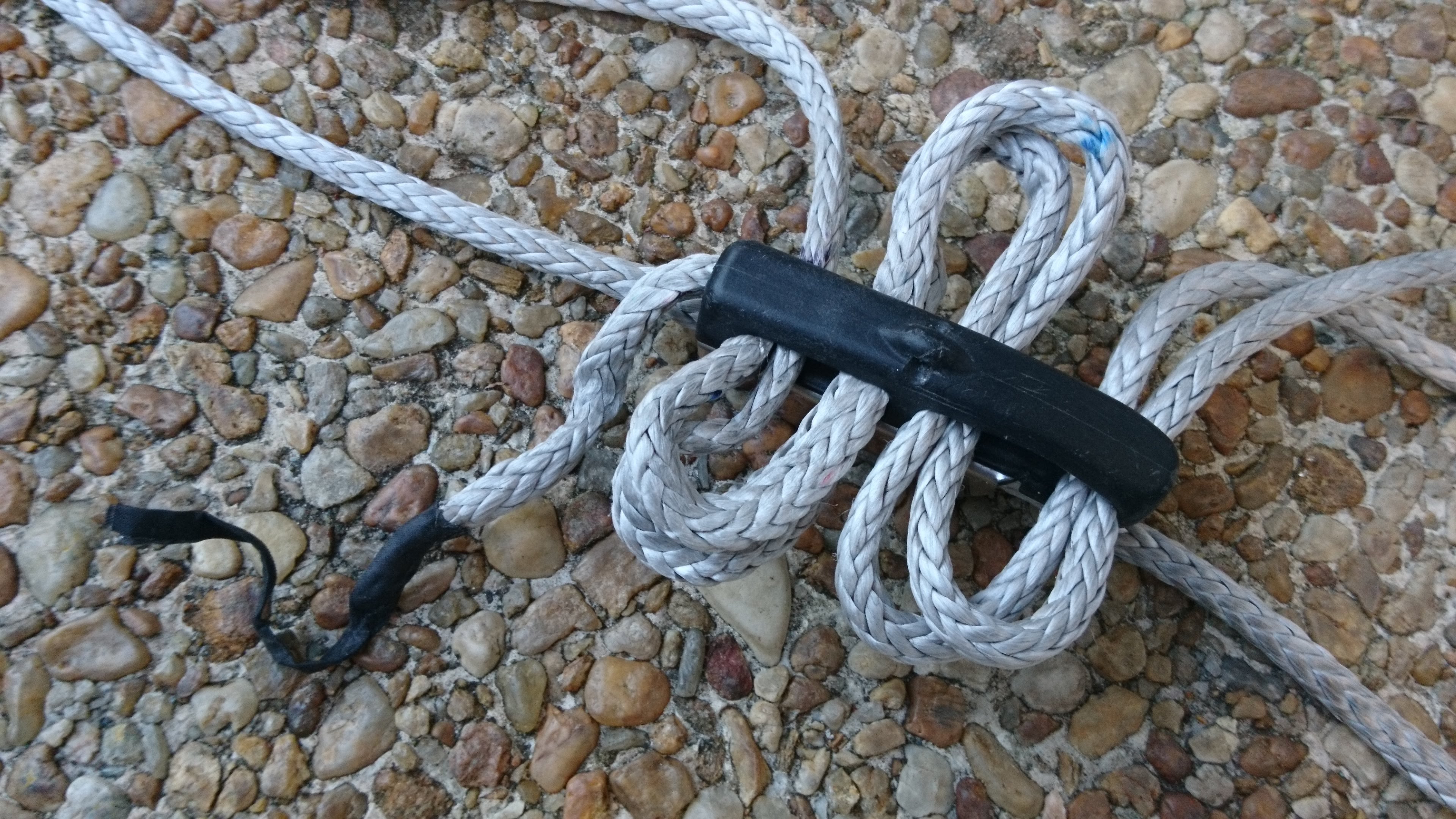
Route the 5cm of trim line tail through the loops along the side of the serpentine.
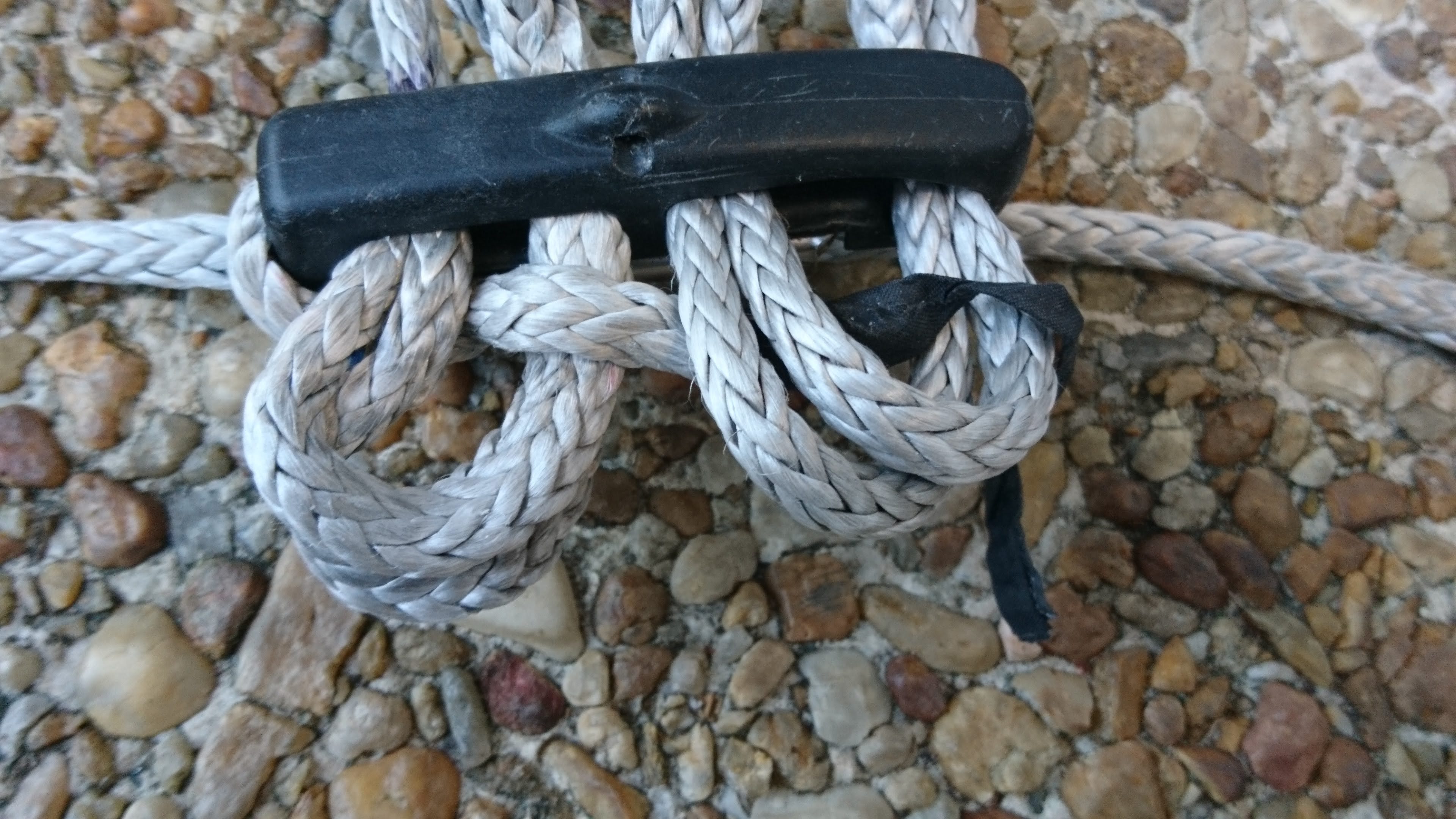
Make sure the insignia cloth tail is also routed through these loops. Holding these pieces in place, pull the trim line slack down through the cleat grooming the lines as you go. Keep the lines as parallel as possible.
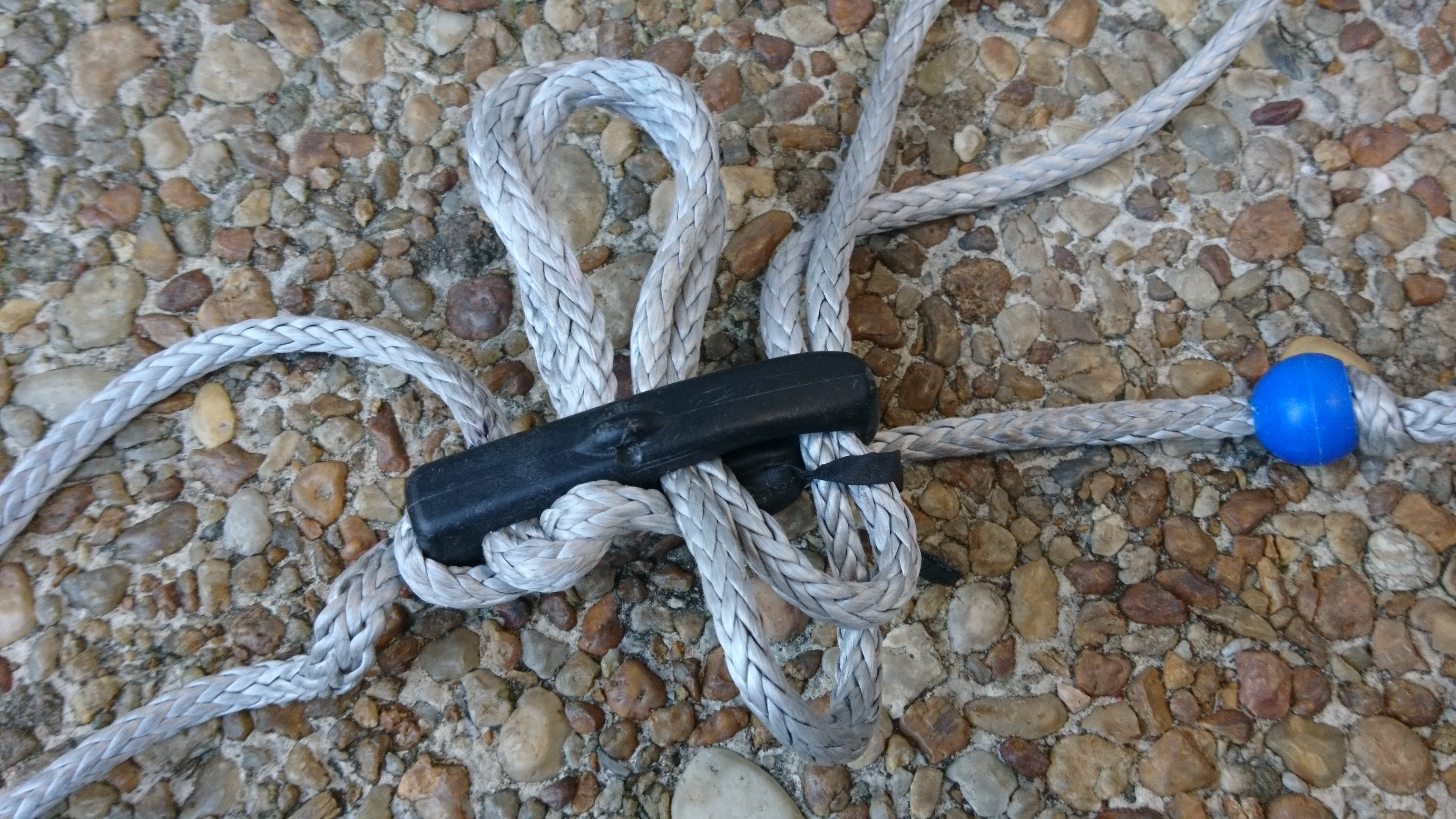
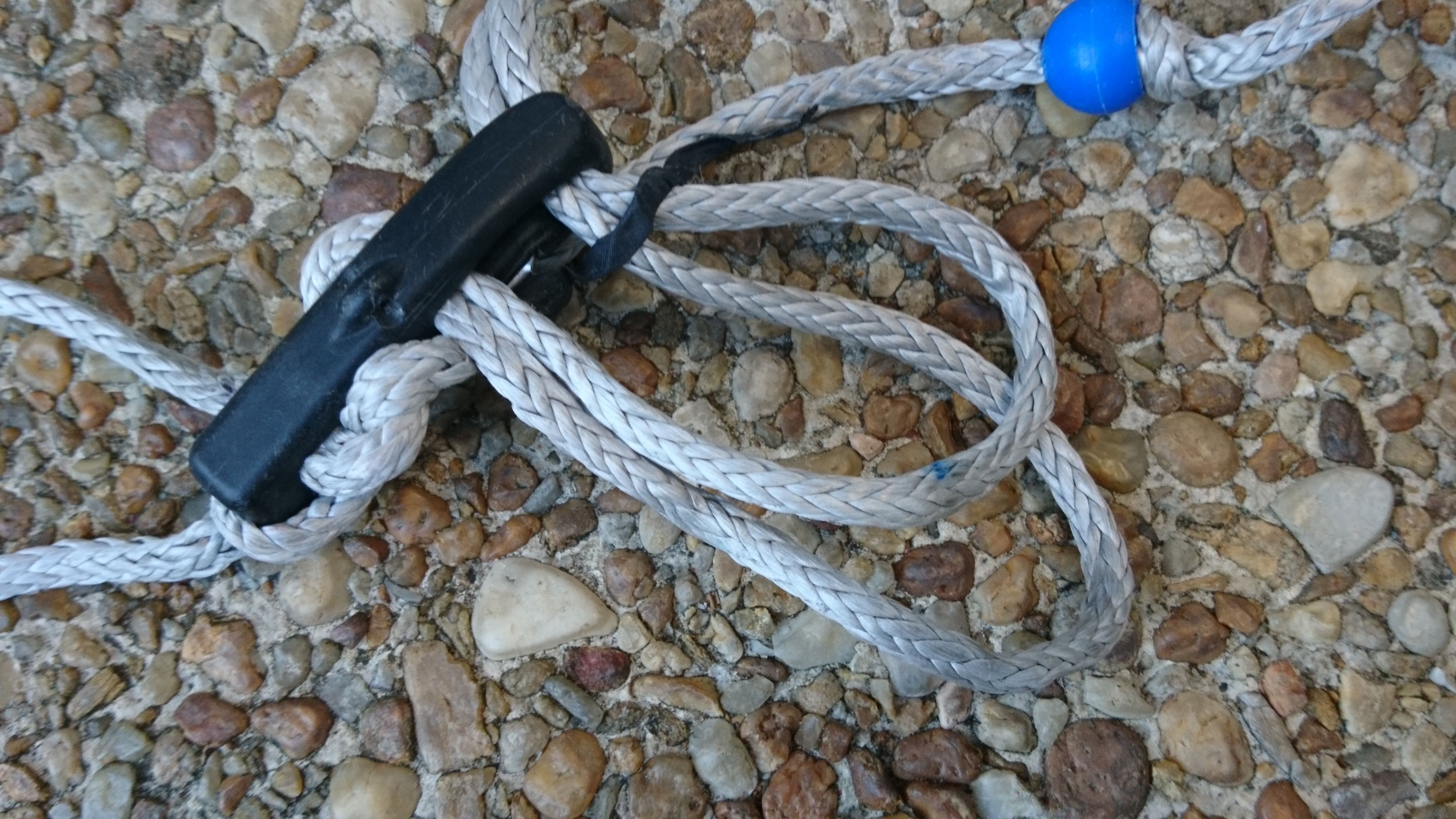
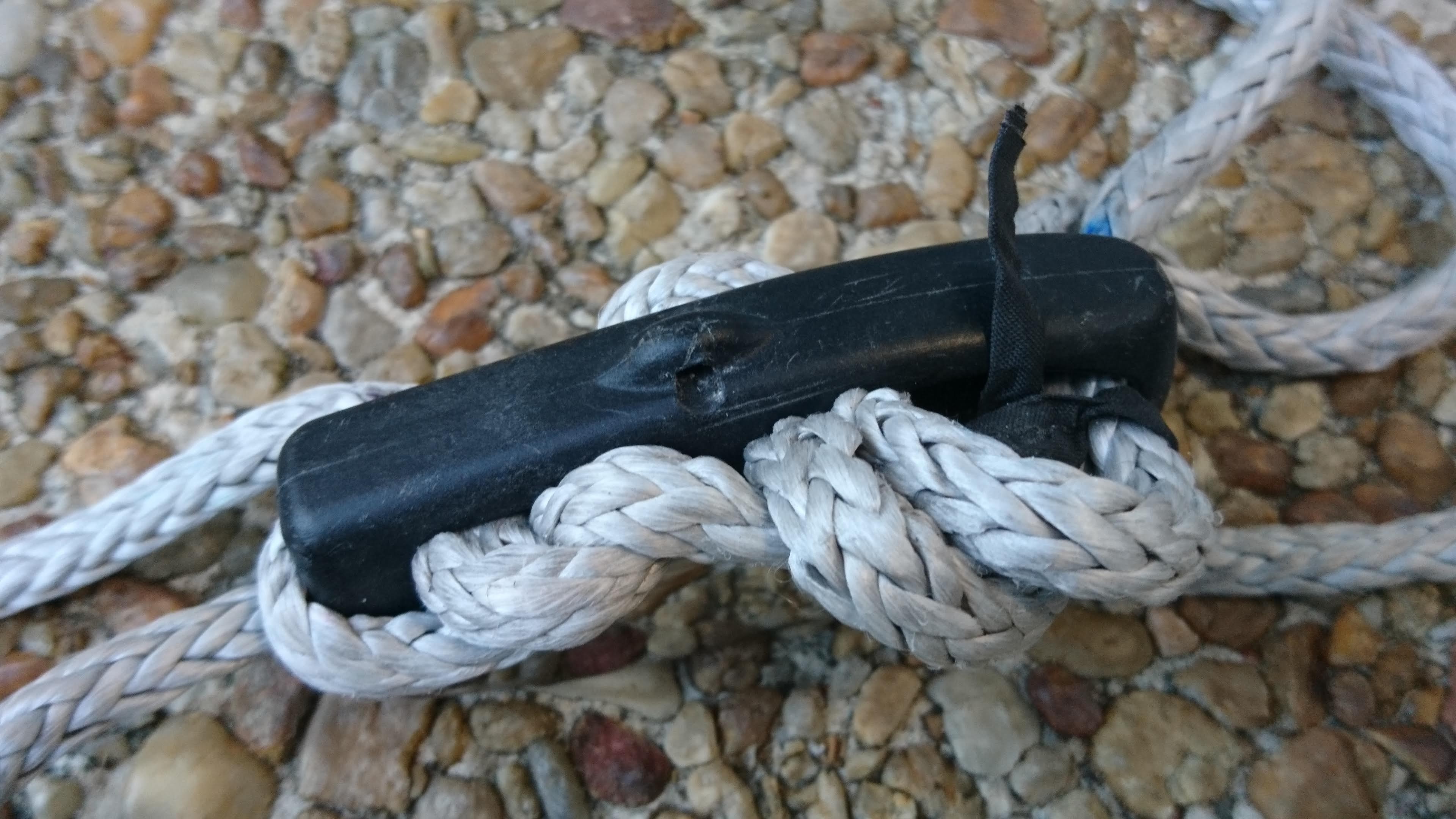
With the trimline tight in the serpentine path, have a friend help you put the trim line in tension. Then slide the stopper up and down the trim lines to even up the slack in the pair of trim lines.
You’ll want to verify you can reach the trimline end under normal flying conditions. To do this, put your harness on, clip the trim line into the harness and have a friend pull on the trim line by the separation block. They should pull the bar to your side about 30 degrees above horizontal. Verify you can reach the jaws of the cleat and grab the trim line tail without over-reaching. If you have to stretch to reach the tail, the cleat is too far away. You can move it closer by moving some of the trim line up through the cleat. For each centimeter you need to move the cleat down, you’ll need to move two centimeters of line through the cleat. Making this adjustment is a bit tedious, but the trim line tail must be in easy reach under load.
Attaching the flying lines
With the trim line routed, the flying lines can be attached. Use a about 100mm of a 3mm line to folded and tied with an overhand knot to form a stopper for one of the main flying lines. Route this flying line down through the separation block and attach the stopper to the end-loop of the flying line with a larks head.

Route the other flying line through the remaining hole in the separation block. Continue routing it through the stopper block and then the bar. Attach the flag line to the flying line with a larks head. Pull flag line up through the bar and stopper block with flying line.
Steering lines
For the back lines of the kite, the bar is equipped with a short pigtails one each end. Each pigtail is made from 350mm of 600# Spectra or 1/16 inch Ultrex folded in half and tied with an overhand knot. Once tied, the working length of the pigtail is about 145mm. Each pigtail is pulled through a drilled hole at the end of the bar leaving the knot on the pilot side.
The steering lines are attached to the pigtails via long leaders of 600# Spectra or 1/16 inch Ultrex. Each leader is made from 1055mm of line with a spliced and stitched loop on one end and an overhand knot on the other. The effective length of a leader from loop end to knot is 810mm.
Use a larkshead to attach the loop of each leader to the loop of its steering line. Then attach the knot of the leader to the loop of the pigtail with a larks head. Keeping the knot of the leaderline next to the bar minimizes the risk of snagging the steering lines in the components of the bar.
With all the lines attached, the trim control let all the way out and the bar pulled all the way back, the tips of all four flying lines should converge to the same point.
Successful variants
What I have described above uses a single, continuous piece of 4mm Amsteel Blue about 2275mm long. I have also had good success using a shorter segment of Amsteel below the cleat with a 6mm line above the cleat to form the trim line. The lines are joined by loops on spliced ends at the top of the cleat. The 6mm line is more comfortable to grip, but this design doesn’t allow for much variation of the cleat position on the trim line. If the cleat position is wrong, a new trim line would need to be made with a more favorable ratio of 4mm to 6mm line.
Failed variants
I have also tried variants of this rig that offer longer trim line tails. One used the standard 2-1 mechanical advantage described above but had a longer tail that could be reached at the bar even when trimmed out. The other used a 4-to-1 mechanical advantage that provided minimal tail when trimmed out. In each case, the additional length of trim line was a tangle hazard. The extra line could easily compromise bar spin, trim control, and kite steering. I have phased these variants out of my gear in favor of the 2-to-1 mechanical advantage with the short, magnetized trimline end described above.
