Chapter 3 Assembly
3.1 Bar assembly and threading line
To thread the trim line, put the threaded end through the cleat, entering at the jam side. Exit the cleat at the top, routing up through the low friction ring of the separation block. Reenter the cleat and go through its serpentine path. Leave just enough line above the cleat to provide the desired trim. Route the line through the cleat bead. Go down through the center of the bar, through a ~25mm ball to retain the trim line in the bar. Then go back through the center bore of the bar and through the cleat bead. Slide the cleat beaddown towards the bar to leave lots of slack next to the cleat. Before going any further, make sure the line already passing through the cleat’s serpentine has 5 cm of loop on each side of the cleat. You’ll need this slack in the next step.
Then route the loose end of the trim line up through the cleat’s serpentine path. You want to make large parallel loops of line going back and forth through the serpentine. Route about 5cm of the trim out of the top of the cleat.
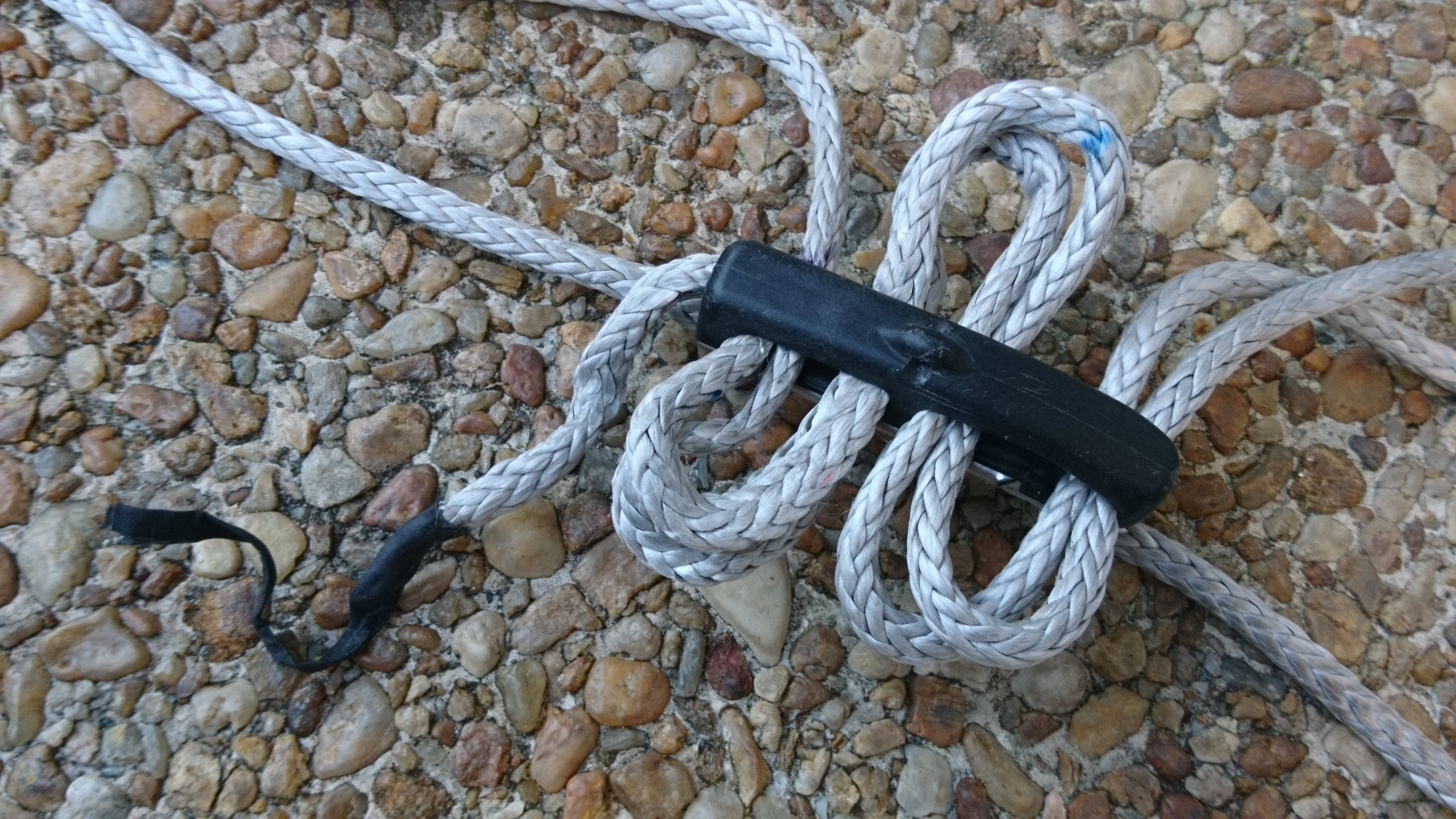
Figure 3.1: Form large parallel loops of line on each side of the cleat’s serpentine path. Route about 5cm of the trim out of the top of the cleat.
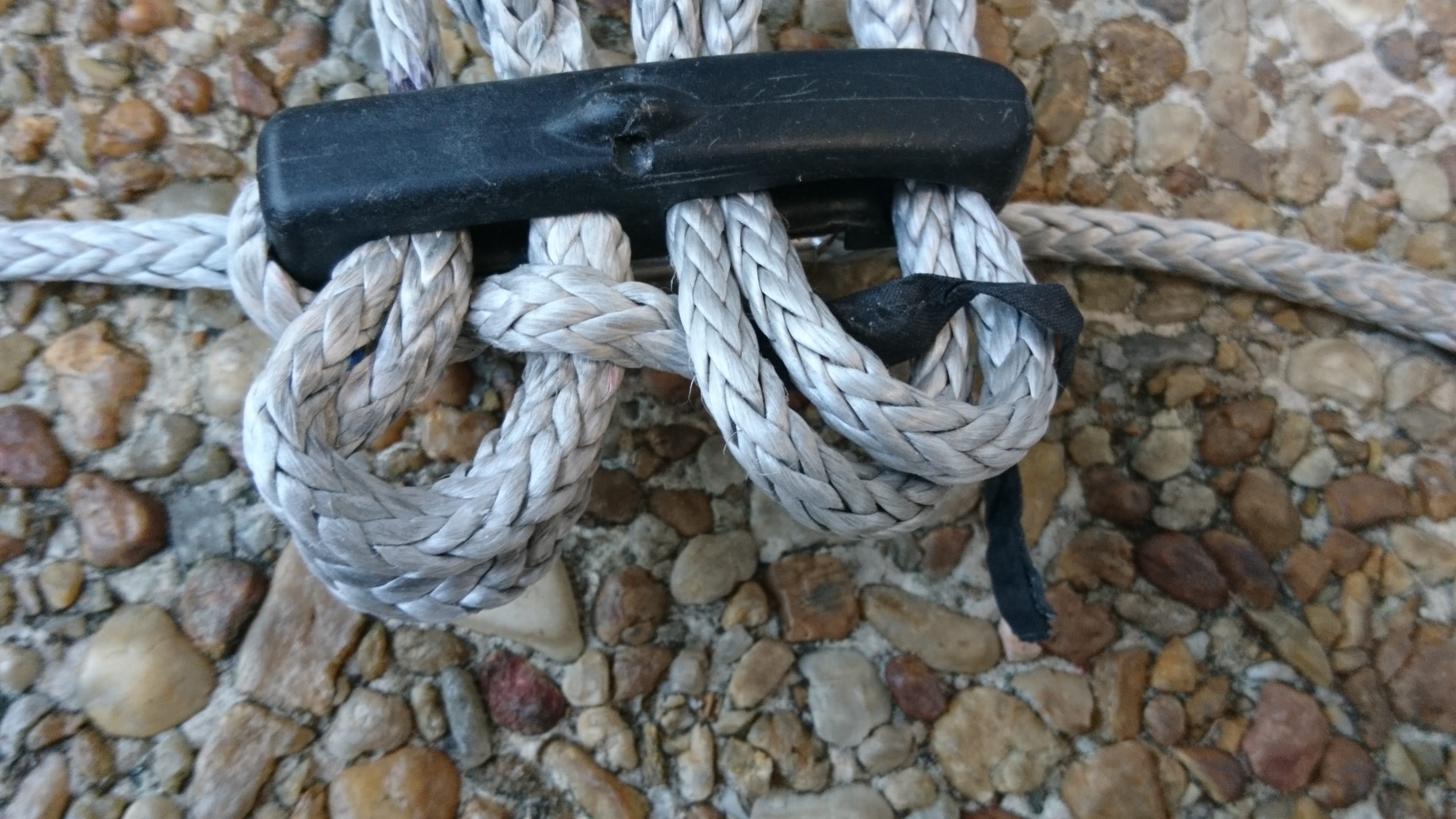
Figure 3.2: Route the 5cm of trim line tail through the loops along the side of the serpentine.
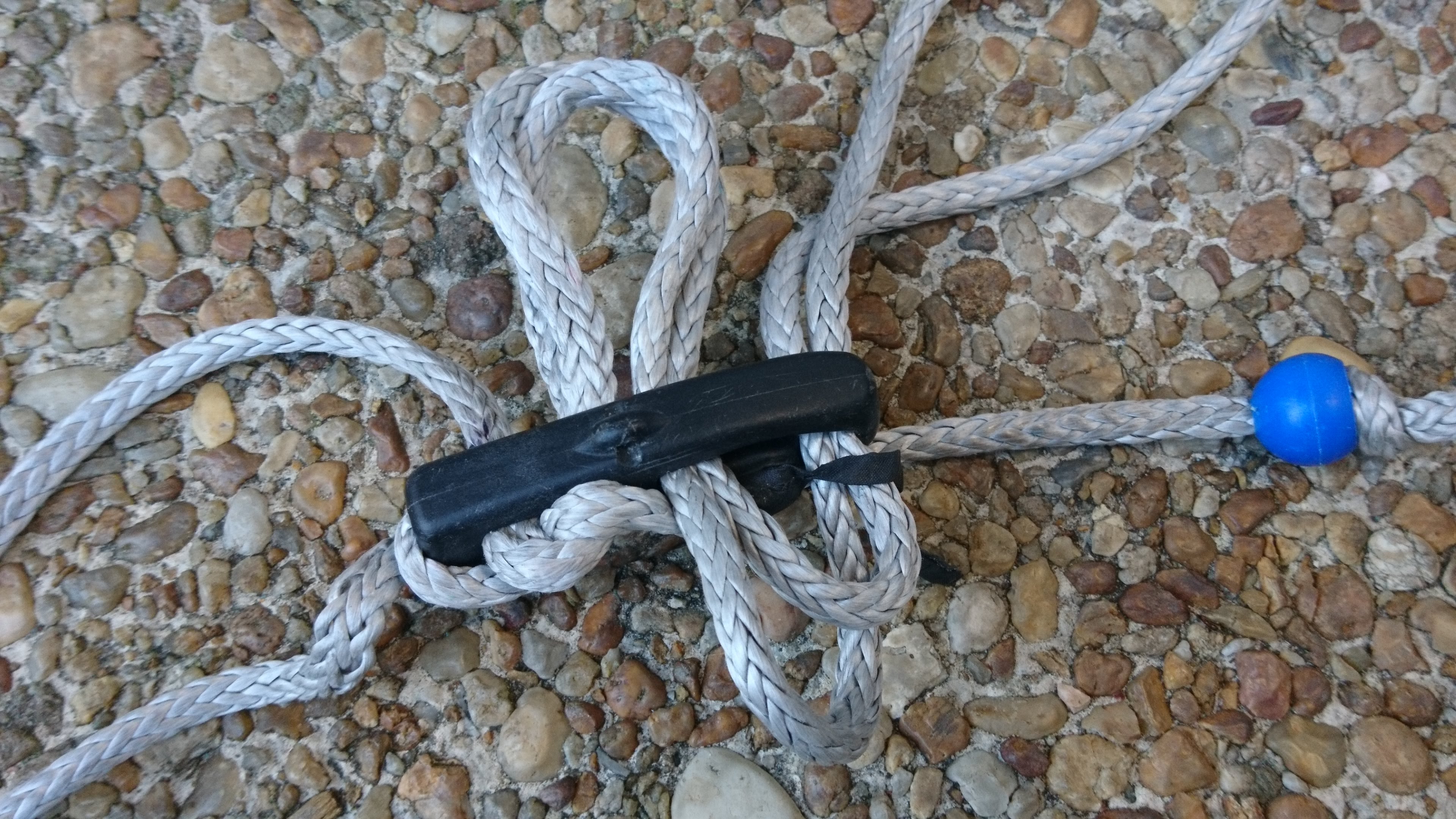
Figure 3.3: Route the insignia cloth tail through the loops. Holding the tail in place, pull the trim line slack down through the cleat grooming the lines as you go. Keep the lines as parallel as possible. Take the slack out of the trimline loops 1 of 3.
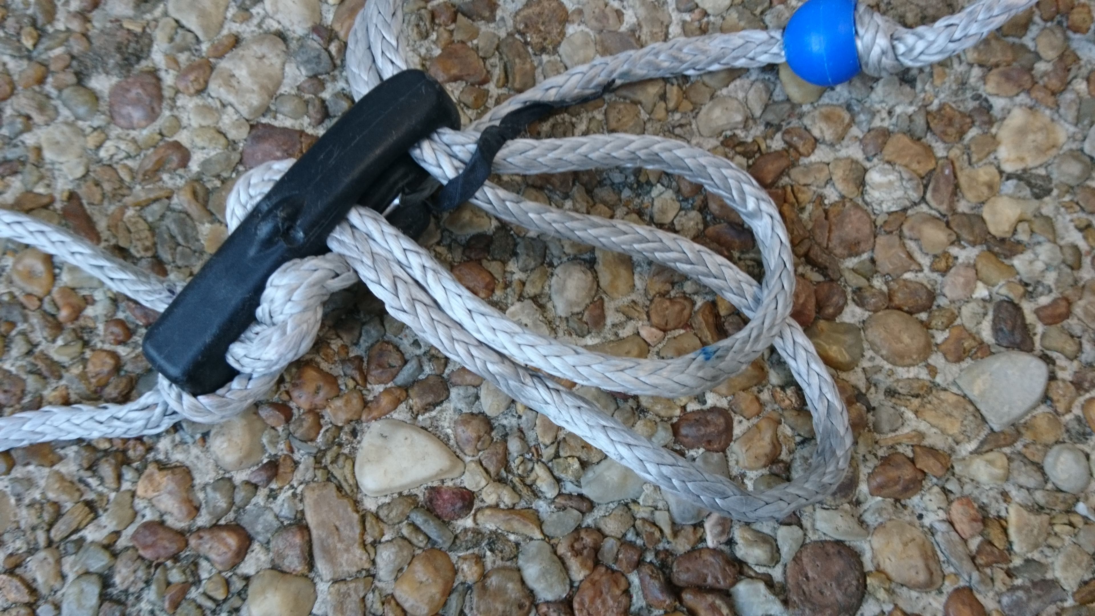
Figure 3.4: Take the slack out of the trimline loops 2 of 3.
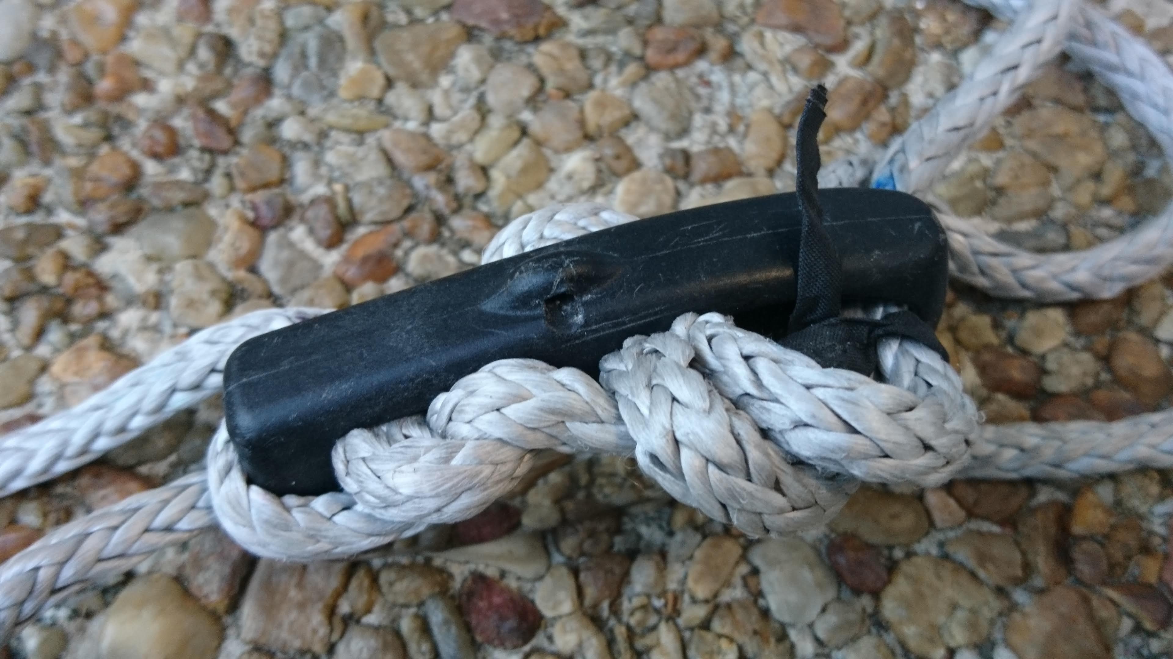
Figure 3.5: Take the slack out of the trimline loops 3 of 3.
With the trimline tight in the serpentine path, have a friend help you put the trim line in tension. Then slide the cleat bead up to the cleat. Look at the cleat from the pilot’s point of view and rotatecleat until the jaws are up. Check the rotation of the cleat bead so that the flag line guide path is on the lower left side of the cleat. Pull the trim lines and jam the bead onto the bottom of the cleat.
You’ll want to verify you can reach the trimline end under normal flying conditions. It’s easier to assess the cleat position before the flying lines are attached so pause the assembly for a moment to check and adjust the cleat position. To do this, put your harness on, clip the trim line into the harness and have a friend pull on the trim line by the separation block. They should pull the bar to your side about 30 degrees above horizontal. Verify you can reach the jaws of the cleat and grab the trim line tail without over-reaching. If you have to stretch to reach the tail, the cleat is too far away. You can move it closer by moving some of the trim line up through the cleat. For each centimeter you need to move the cleat down, you’ll need to move two centimeters of line through the cleat. Making this adjustment is a bit tedious, but the trim line tail must be in easy reach under load.
3.2 Attaching the flying lines
With the trim line routed, the flying lines can be attached. Route one the flying lines down through the separation block and attach the stub line stopper to the end-loop of the flying line with a larks head to retain the flying line in the stopper.
Route the other flying line through the remaining hole in the separation block. Continue routing it through the cleat bead and then the bar. Attach the flag line to the flying line with a larks head. Pull flag line up through the bar and bead with the flying line. The routed lines should look like Figure 3.6 at the separation block. The over-all assembly should look like 3.7
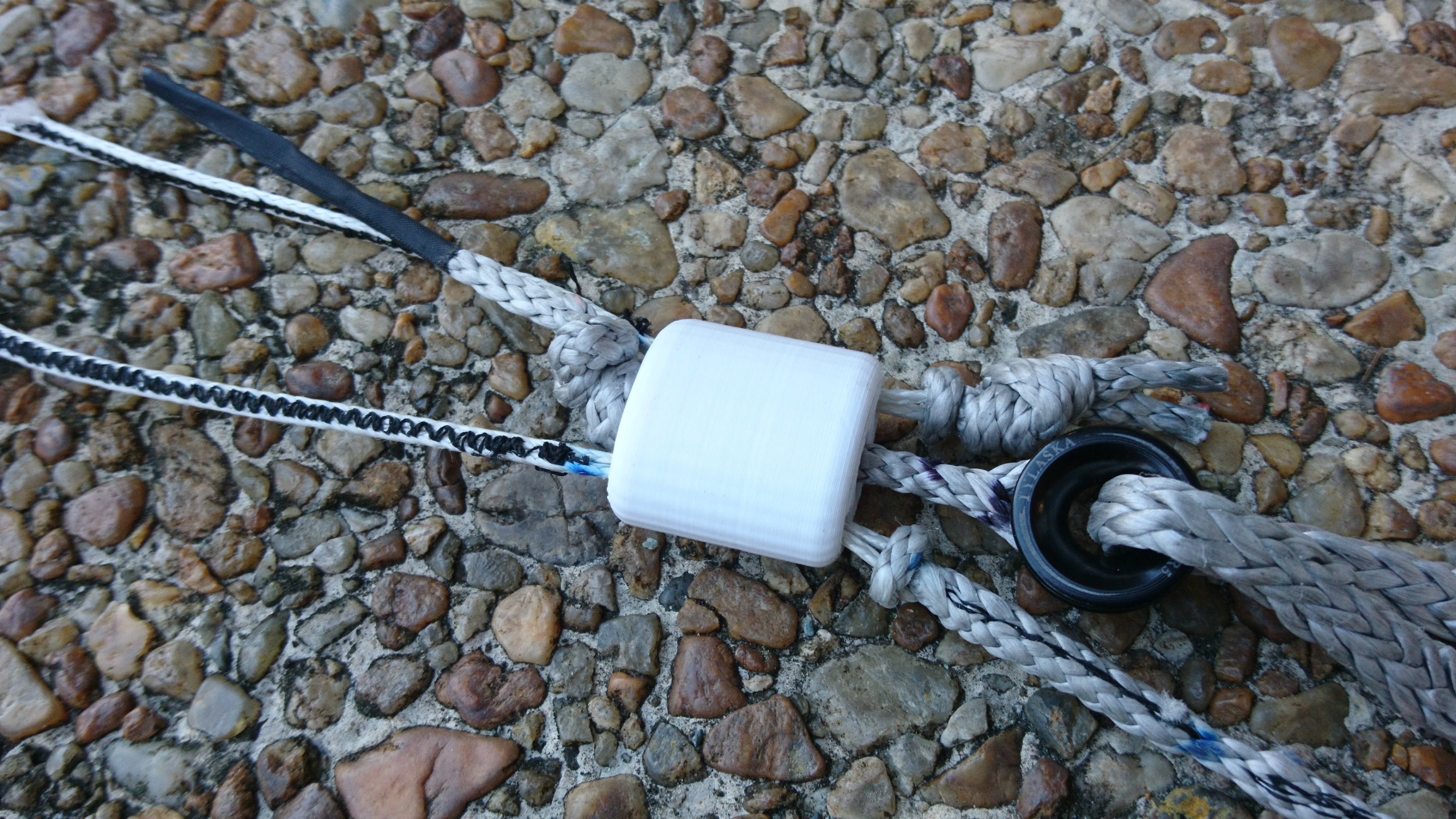
Figure 3.6: The flag line meets the flying line.
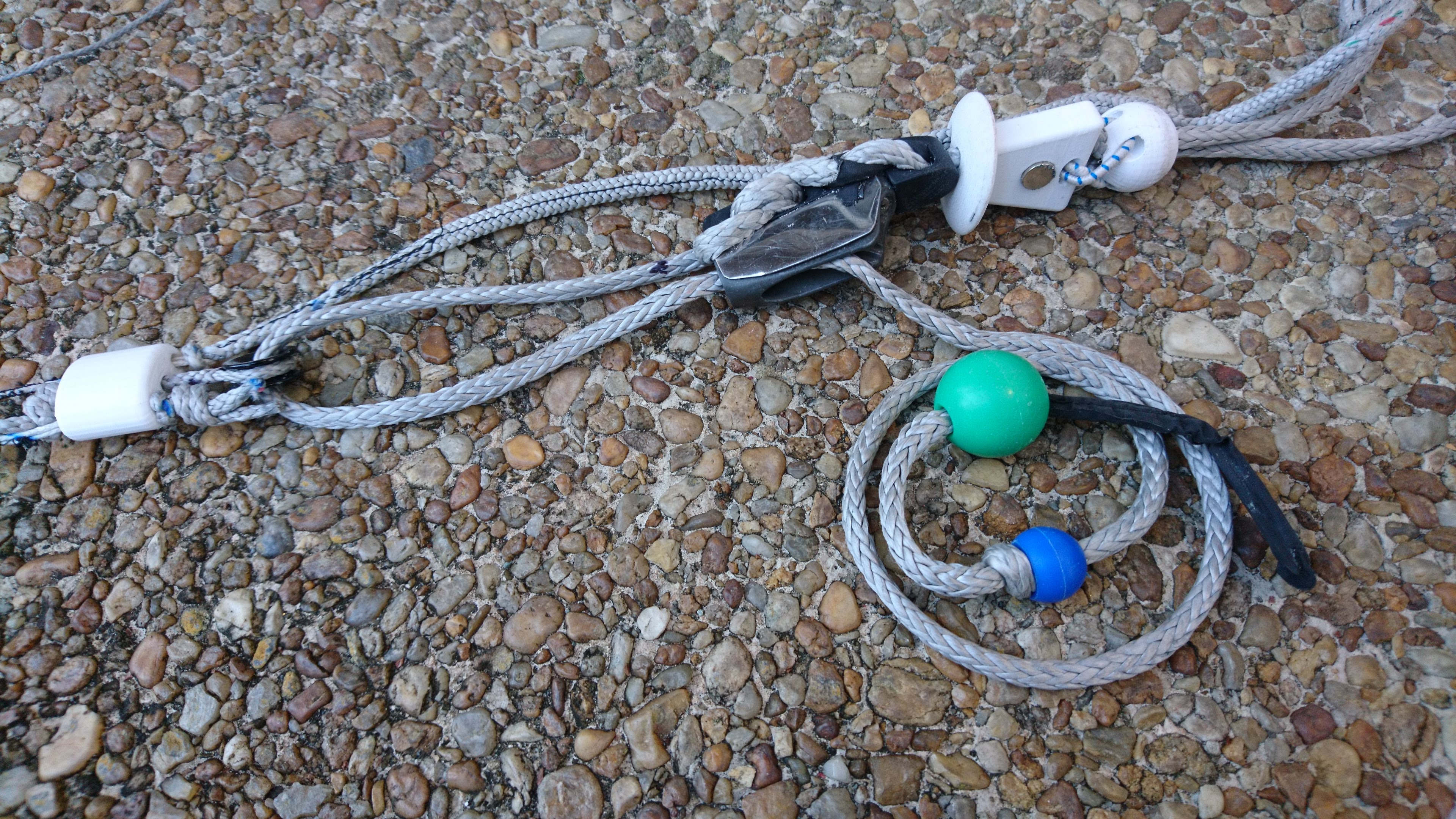
Figure 3.7: Assembled bar
3.3 Bar End Loops
Pull each bar end loop through one of the holes at the ends of the bar. Route the loop from the pilot-side of the bar to the kite side so the knots are left on the pilot side. Make sure both sides of the loop are even and the knot sits flush against the back of the bar.
3.4 Steering line leaders
Use a larkshead to attach the loop of each steering line leader to the loop of its steering line. Then attach the knot of the leader to the loop of the bar-end loop with a larks head. Keeping the knot of the leaderline next to the bar minimizes the risk of snagging the steering lines in the components of the bar.
With all the lines attached, the trim control let all the way out and the bar pulled all the way back, the tips of all four flying lines should converge to the same point.